



An RFQ may ask for an “automatic liquid filling line” while leaving the start and end points undefined. One supplier may quote an infeed conveyor, filler and capper. Another may include bottle feeding, rinsing, cap sorting, connecting conveyors and line controls. The equipment names look similar, but the operating responsibilities and total scope are different.
A buyer should define the container journey before comparing prices. This article follows the primary packaging section from empty-container infeed through filling, closure application and discharge conveying. It also identifies equipment that may connect to this section but should not be assumed to be included.
The scope boundary is the physical and functional point where the supplier’s responsibility begins and ends. A clear boundary answers four questions:
In what condition does the empty container arrive?
In what condition must the filled and closed container leave?
Which machines, conveyors, sensors and controls create that change?
Who supplies each mechanical, electrical, product and control interface?
For example, “container available on the infeed conveyor at an agreed height and pitch” is a more useful start point than “bottle feeding included.” At the discharge end, define whether the supplier hands over a filled and closed bottle on a powered conveyor, at a transfer plate, or at the inlet of an existing labeler.

The infeed section supplies containers at a rate and spacing the filling section can accept. Its scope depends on how bottles or other containers arrive at the line. They may be placed manually on an accumulation table, delivered by an unscrambler, transferred from a depalletizing system, or supplied directly from bottle-making equipment.
The quotation should name the included infeed equipment rather than use “automatic feeding” as a general description. Confirm the conveyor type, working height, direction, usable accumulation, guide arrangement, container detection and transfer point. Lightweight, tall or shaped containers may need format-specific support.
When PET containers are made on site, the handoff from the PET blow molding machine must be defined. The parties should agree who supplies the connecting conveyor, how bottles are buffered, and what signal is exchanged when the filler is blocked or starved.
Rinsing or other container preparation is application-dependent and should not be added by assumption. The required method follows the container condition, beverage process and hygiene plan. A new container arriving directly from a controlled upstream process presents a different requirement from a returned bottle or a container stored before filling.
If preparation is included, the scope should state the method, media supply point, drainage boundary, container handling and change parts. It should also define who supplies any treatment medium, filtration, recovery or exhaust arrangement required by the confirmed process. The supplier needs container drawings and samples to check inversion, gripping, neck support and drainage behavior where relevant.
The filling machine needs a defined product condition at its inlet. The buyer should provide the beverage type, whether it is still or carbonated, relevant viscosity or particles, filling temperature, foaming behavior and required fill basis. The quotation should then identify the product inlet connection and any local tank, valve, pump, piping or control components included within the filling scope.
Processing equipment is normally a separate project block unless the quotation specifically includes it. Water treatment, beverage preparation, thermal processing, carbonation and product storage should therefore be shown as upstream systems or interfaces, not hidden inside the phrase “filling line.” Yaos Machinery lists related upstream equipment under its pretreatment system range, but the required process must be confirmed for each beverage.
The filler is selected around the confirmed product, container, fill requirement and output. Its physical scope may include the main frame, product-contact path within the machine, filling valves or nozzles, container handling, local controls and guarding. The proposal must state the exact configuration rather than extend one model’s description to every beverage application.
Container transfer is part of the functional design. Inline systems may index containers under filling positions before releasing them to the next station. Rotary or monoblock configurations may use dedicated transfer components between operating zones. In either case, the supplier must know every container size, neck or opening, base geometry and required changeover.
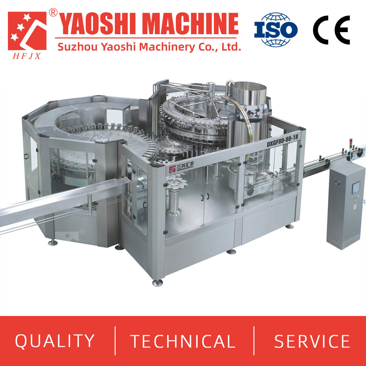
Buyers can review Yaos Machinery’s liquid filling equipment categories as a product reference. Final suitability, filling method and supported formats still require confirmation against project data and samples.
“Capping included” does not define the closure system. The quoted scope should separate closure loading, elevation, sorting, delivery, placement and final closing. A plant may accept manual loading into a hopper but still require automatic orientation and delivery to the capper. Another project may expect a bulk closure feeding system from floor level.
Send a controlled closure drawing and representative samples with the container drawing. State whether the package uses a plastic screw cap, press-on closure, crown cap, can end or another confirmed format. The supplier should return the applicable feeder, chute, pick-off or placement method, closing device and container-holding arrangement. Do not assume that one closure system can run different caps because their nominal diameter appears similar.
The transition from filling to capping also needs a defined rule for uncapped containers. Confirm spacing, acceptable accumulation, spill handling, missing-closure detection and the response to a capper stop. These details affect whether the filler stops immediately, slows down where supported, or continues only for an agreed buffer condition.
Conveyors do more than move bottles between machine frames. They establish spacing, provide short-term accumulation and carry blocked or starved signals between stations. The line layout should identify each powered conveyor, transfer plate, guide rail, drive, sensor and local control included in the supply.
At minimum, confirm:
line direction and conveyor working height;
container condition and required pitch at every transfer;
available accumulation before and after the filler or capper;
maximum acceptable back pressure for the package;
motor and control-panel responsibility;
start, stop, ready, blocked, starved and fault signals;
the exact discharge interface to the next machine.
Accumulation can absorb short interruptions, but it cannot correct a downstream machine that is permanently too slow for the agreed production duty. Each station must be evaluated using the same product, container and operating basis.
| Line area | Possible scope status | What the quotation must confirm |
|---|---|---|
| Empty-container infeed | Included, optional or buyer interface | Loading method, accumulation, conveyor, transfer point and control signals |
| Container rinsing or preparation | Included only when required by the confirmed process | Method, media, drainage, handling and responsibility for supporting services |
| Product inlet and local product path | Core filling scope with a defined upstream boundary | Connection point, included tank or pump, instrumentation, piping and cleaning boundary |
| Filling machine | Core scope | Confirmed product, container, fill basis, format range, output basis and change parts |
| Closure loading, sorting and delivery | Included or optional by agreed automation level | Operator loading point, feeder, chute, low-closure response and supported closure |
| Capping or sealing | Core scope when a closed package is the discharge requirement | Application method, tooling, container holding, inspection boundary and change parts |
| Connecting and discharge conveyors | Included to the stated handoff point | Lengths, heights, drives, guide rails, accumulation and controls |
| Labeling, coding and inspection | Optional or downstream interface | Whether supplied, excluded or connected to existing equipment |
| Secondary packaging | Normally outside this core scope unless expressly included | Transfer point, pack format, design rate and supplier responsibility |
Mechanical connection does not create a coordinated line. Each module needs a defined response when the preceding machine stops supplying containers or the next machine stops accepting them. The controls schedule should state signal direction, normal state, fault state, restart logic and responsibility for cables and programming.
Emergency stops and guarding also require a boundary. Confirm whether one emergency stop halts the entire supplied section or only a defined zone, and how third-party machines participate. The final design must follow the agreed site and project requirements; the article does not establish a universal safety architecture.
Labeling, coding, inspection and secondary packaging affect the discharge interface even when they are outside the automatic liquid filling line supply. The buyer should still provide the next machine’s inlet height, speed, control requirements and acceptable bottle condition.
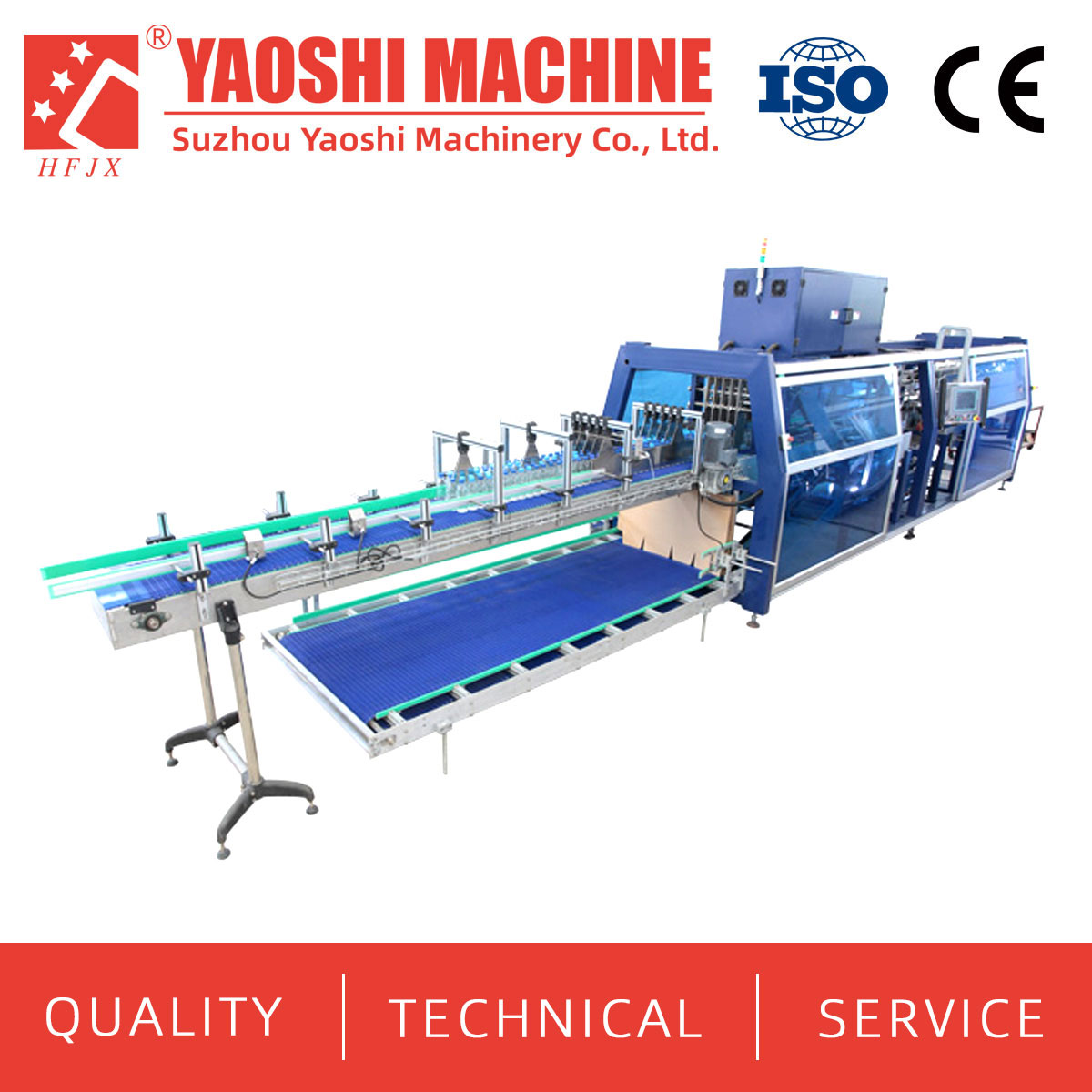
If these downstream modules are part of the project, define them as separate scope blocks. The label material and bottle geometry guide the selection of automatic labeling equipment. Coding, inspection and packing should each have their own input data, acceptance criteria and interface point. This preserves a clear filling-line boundary while preventing downstream requirements from being discovered after the layout is fixed.
Create one line-by-line scope matrix using four status labels: included, optional, buyer supplied and excluded. For every interface, name the equipment owner, connection point, design condition, utility or signal requirement and acceptance evidence. Attach the matrix to the commercial offer so that later drawings and revisions follow the same boundary.
The matrix should cover physical transfers, product piping, drainage, electrical power, compressed air, communications, guarding and operator material loading. Existing equipment needs extra detail: maker and model, layout, conveyor elevation, direction, current operating rate, control drawings and recent photos or video of the handoff area.
Acceptance should test the supplied system, not isolated machines under unrelated conditions. Agree which beverage or test medium, containers, closures and formats will be used. State the expected operating sequence, sustained output basis, normal replenishment, deliberate stop conditions and restart procedure.
If an existing labeler or site utility is unavailable during factory testing, separate what can be demonstrated before shipment from what must be verified after installation. The quotation should name each dependency and the party responsible for providing it. This avoids treating an untested third-party interface as proof of complete-line performance.
The core scope may include container infeed, preparation or rinsing where required, filling, closure feeding, capping and connecting conveyors. The quotation must define the exact modules and handoff points; there is no universal package.
They are upstream process blocks unless the proposal expressly includes them. Define the beverage condition and connection point at the filler inlet.
Not automatically. Confirm whether an operator loads a local hopper or whether the supply includes a bulk feeder, elevator, sorter and delivery chute.
List each section’s length, width or chain type where relevant, height, direction, guides, drives, sensors, accumulation function, controls and exact transfer point.
It can be evaluated after the supplier receives the labeler’s inlet height, direction, supported speed, container-spacing requirement, control signals and available accumulation.
No. They may be included as separate project modules. This article treats them as optional downstream blocks so the filling-line boundary remains clear.
Agree representative product, container and closure combinations before ordering. Include difficult or limiting formats rather than testing only the easiest package.
Provide the product and filling conditions, container and closure drawings or samples, output by format, required start and end points, factory layout, utilities and existing-equipment interfaces.
For a new automatic liquid filling line, an expansion or a connection to existing equipment, send Yaos Machinery the product details, container and closure drawings or samples, target output for each format, factory layout and the required upstream and downstream interfaces. Mark which modules you expect to be included, optional, buyer supplied or excluded.
Ask for an equipment list, line layout, interface matrix and quotation scope. Email tony@yaos.ltd or call/WhatsApp +86 18915689808.


+86-512-58530618

Wukesong Road, Sanxing Town, Zhangjiagang City, Jiangsu Province, China


