


A bottled water factory is not defined by the filling machine alone. Raw-water intake, treatment, hygienic storage, bottle supply, rinsing, filling, capping, inspection, labeling and packing must work as one controlled process. If one module is specified against a different flow rate or package, the plant may produce less saleable water than the headline BPH suggests.
For a greenfield bottled water production line, the investor should begin with evidence about the water source and the finished product, then define the bottle, output and market pack. Equipment selection comes after those inputs are controlled.
The project can begin at the raw-water source, at a raw-water tank or at a prepared-water connection. It may end after capping, after secondary packaging or at a finished pallet. State those boundaries before comparing quotations.
| Project block | Possible equipment scope | Buyer input |
|---|---|---|
| Raw-water intake | Transfer pumps, buffer tank, initial screening, source monitoring and inlet pipework | Source type, analysis, seasonal variation and available flow |
| Water treatment | Pretreatment, membrane or other purification stages, dosing, disinfection and treated-water storage as required | Raw-water report, finished-water objective and local requirements |
| Bottle supply | PET blowing and transfer, or handling of purchased empty bottles | Bottle and preform drawings, formats and supply strategy |
| Fill and close | Rinsing, filling, capping, cap feeding, conveyors and basic inspection | Water, bottle, cap and stable-output requirement |
| Label and code | Labeling, date or batch coding, inspection and rejection | Artwork, label material, code content and bottle orientation |
| Pack and palletize | Film, tray or carton packing, pack conveying, palletizing and load wrapping | Pack pattern, pallet pattern, warehouse and dispatch method |
Every item should be marked included, optional, excluded or supplied by the buyer. The phrase “complete drinking water production line” is not a substitute for an itemized equipment and responsibility schedule.
The treatment process depends on what enters the plant and what the packaged product must be. A municipal supply, well, spring or other approved source can present different suspended solids, hardness, dissolved minerals, organic load, disinfectant residuals and microbiological risks.
Obtain a representative laboratory analysis and identify seasonal changes or different operating conditions.
A mineral water production line should not automatically be specified like a purified-water plant. If mineral composition is part of the intended product identity, treatment choices need to follow the source, finished-water objective and regulatory position. Likewise, reverse osmosis should not be included or omitted merely because it appears in a standard equipment package.
The source must supply enough water at the required conditions for production, cleaning and the confirmed treatment process. Define the inlet flow, pressure, temperature, available hours and interruption risk.
A raw-water buffer may separate variable source delivery from steady treatment demand. Its usable volume, level control, sanitation, overflow and drainage should be specified.
Do not size intake equipment from packaged-water output alone. Treatment reject streams, filter backwash, rinsing, cleaning and other verified uses can increase the total source-water demand.
A water treatment system may include several stages, but no fixed sequence is suitable for every plant. Each module should have a stated purpose, design inlet condition and acceptance check.
| Treatment function | Information required | Scope question |
|---|---|---|
| Particulate control | Turbidity, suspended matter and source variability | Which filtration or clarification stage is required? |
| Hardness or scale control | Hardness, alkalinity and selected downstream process | Is softening, dosing or another control method required? |
| Organic or disinfectant control | Organic indicators, taste or odor concerns and source disinfectant | Which media and monitoring are appropriate? |
| Dissolved-solids control | Full ionic analysis and finished-water target | Is membrane separation or another process justified? |
| Microbiological control | Source risk, storage and hygienic distribution plan | Which barriers, monitoring and response actions are required? |
| Final adjustment | Product specification and labeling basis | Is blending, mineral adjustment or another step part of the project? |
The proposal should provide a process flow, equipment list, operating basis, tank volumes, monitoring points and expected utility demand.
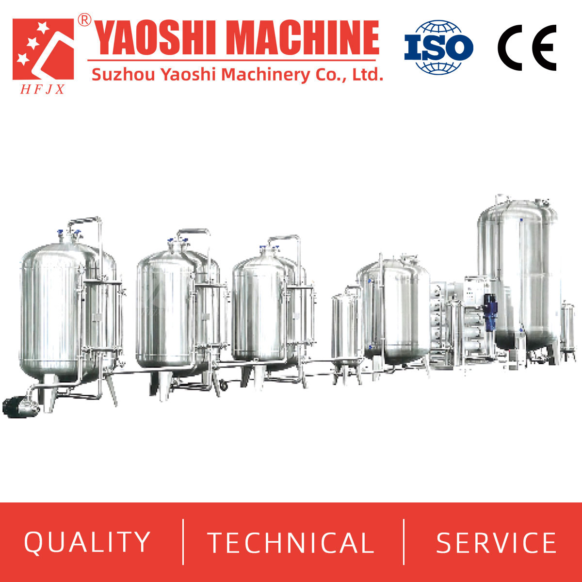
Treatment design starts with source-water evidence.
Gross feed-water flow is not the same as net water available for bottling. Ask the treatment supplier to state the net treated-water output under the agreed raw-water conditions.
Hourly product-water demand can be estimated from bottle volume and stable filler output:
Hourly filled-water volume = bottle volume × stable bottles per hour
Calculate every bottle format separately. Add the confirmed demand for bottle rinsing, product displacement, cleaning or other uses, while keeping process water distinct from saleable product water. Treated-water storage should support the production schedule without creating excessive residence time or an uncontrolled hygiene risk.
Treatment is not complete when water leaves the final skid. Tanks, pumps and distribution pipework must maintain the required condition up to the filler. Define product-contact materials, tank design, level control, vent treatment where required, recirculation or turnover strategy, drainability and sanitation method.
The battery limit should state who supplies interconnecting pipework, supports, valves, instruments and field installation. If the treatment and filling sections come from different suppliers, assign one party to define and verify the interface.
A PET bottled-water project can use purchased bottles or produce bottles from preforms. The commercial choice changes factory space, utilities, storage, labor and line-integration responsibility.
Define how bottles arrive, remain protected in storage and enter production. Different delivery formats require different unpacking or unscrambling arrangements.
The bottle-making section may include preform feeding, heating, a PET blow molding machine, molds, compressed-air equipment, cooling and empty-bottle transfer. Capacity should be confirmed for the selected bottle and preform, not only a reference format.
Provide bottle volume, height, diameter, neck finish, base design, preform and quality requirements. Define how bottles transfer to filling and how short blower or filler interruptions are buffered. A drinking water production line cannot maintain output if bottle production and filling are specified independently.
The core 3-in-1 water filling machine commonly connects bottle preparation, rinsing, filling and closure application. The quotation should identify the bottle and cap used for the capacity statement, the supported additional formats and the required change parts.
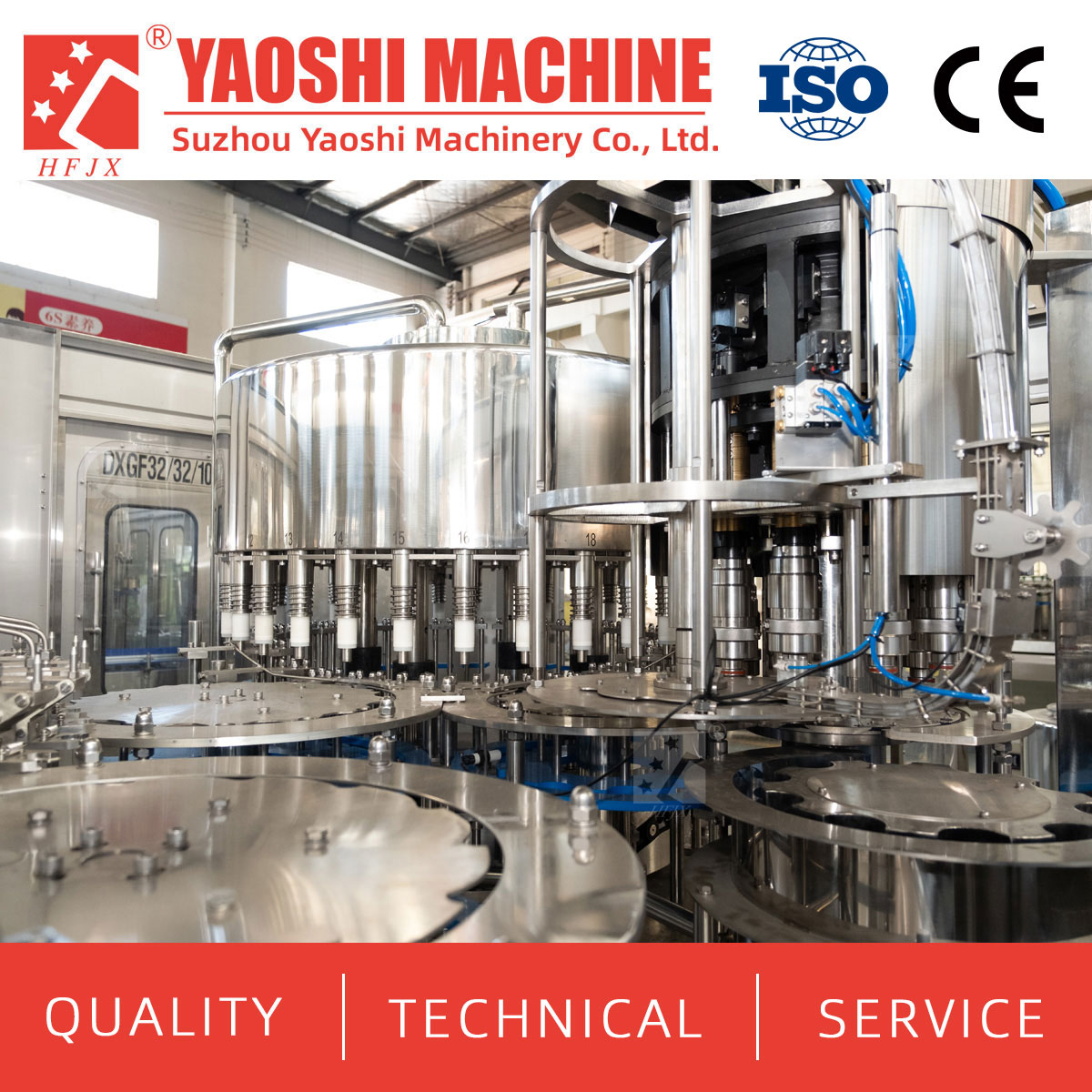
The reference bottle must define filler capacity.
Define:
Water type and filling condition
Bottle drawings, tolerances and approved samples
Neck finish and cap specification
Rinsing medium and drainage requirement
Nominal speed, stable output and good-output measurement point
Cap storage, feeding, orientation and replenishment
Fill-level, closure and leakage checks where specified
Cleaning and sanitation requirements
The filler’s BPH should not be presented as finished-pack output. Downstream losses, material stops and changeovers affect the number of saleable packs produced during a shift.
Conveyors do more than connect machines. They establish bottle spacing, transfer stability and temporary accumulation. The layout should identify air or floor conveying as applicable, guide adjustment, drives, inspection spacing and the control signals exchanged between machines.
Usable buffer time can be calculated as:
Buffer time = usable accumulated bottles or packs ÷ current flow rate
A buffer may allow the filler to continue during a short label or packing interruption. It cannot compensate for a downstream machine whose stable capacity remains below incoming production. Define blocked, starved, reduced-speed, controlled-stop and restart behavior across the line.
Inspection scope should follow the bottle and quality plan. Possible checks include empty-bottle condition, fill level, cap presence or application, label position, code readability and pack completeness. Each rejected item needs a defined rejection method, collection point and production record.
The investor should provide the required code content, location, language and traceability rules.
The labeler should be specified from the approved bottle, label system and stable line output. Bottle shape, label application area, orientation, surface condition and temperature can affect the configuration.
Provide artwork dimensions, label material, reel or magazine data and the number of formats. The quotation should state the included change parts, recipes, material trials and inspection. If labels need replenishment during production, account for the actual change method and expected stop pattern.
Packaging equipment is often rated in packs per minute rather than bottles per hour. Convert the filler requirement using the actual bottle count in each pack:
Required pack rate = good bottles per hour ÷ bottles per pack
Film bundles, tray packs and cartons require different materials, grouping, sealing and discharge arrangements. Calculate each commercial pack separately and identify which format creates the highest demand on the packer.
| Packaging input | Information to provide |
|---|---|
| Bottle | Dimensions, filled weight, stability and orientation |
| Pack pattern | Bottles per pack, rows, columns and required arrangement |
| Material | Film, tray, carton or other approved specification |
| Finished pack | Dimensions, quality checks, code and discharge orientation |
| Production | Required packs per hour, replenishment method and changeovers |
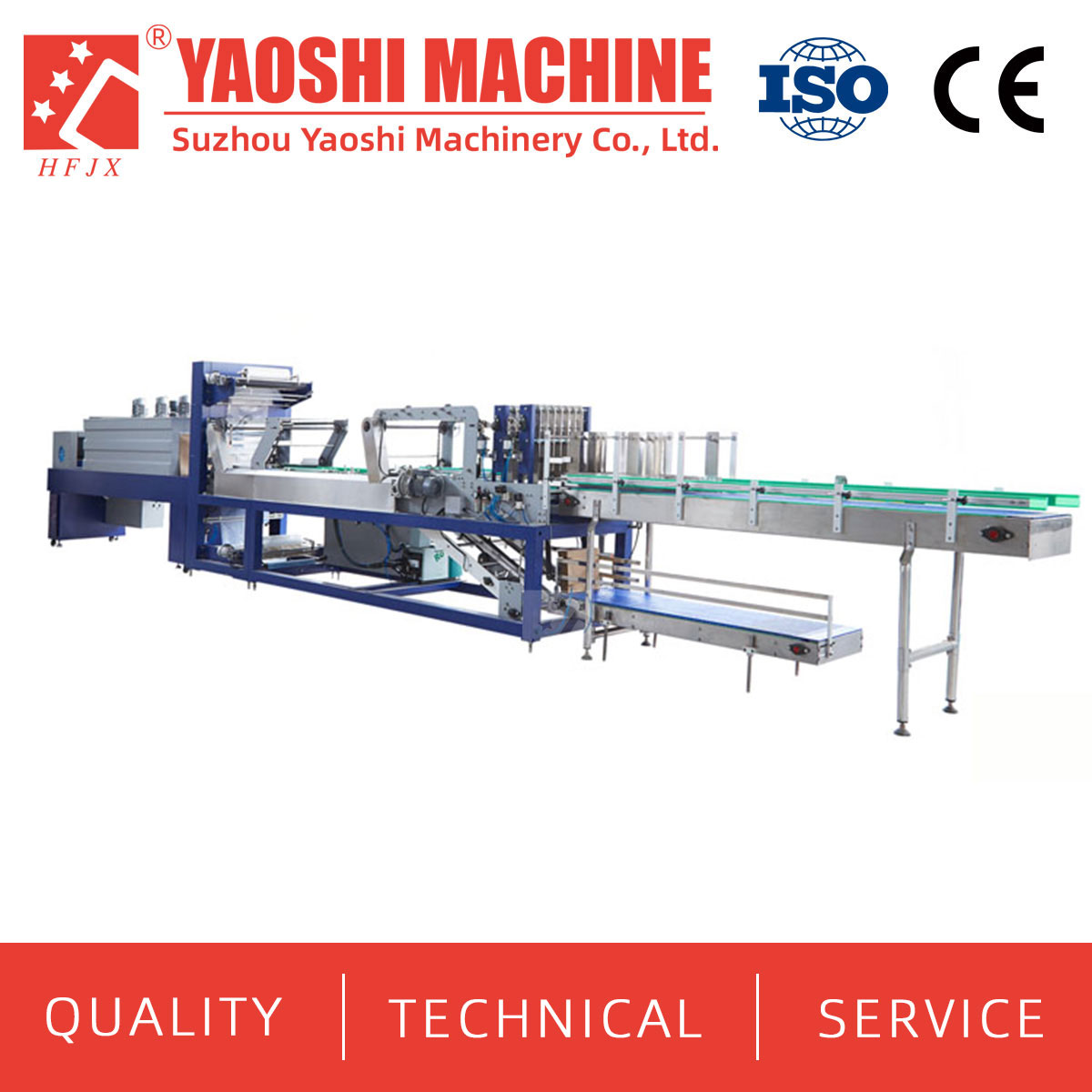
Packer capacity follows the selected pack pattern.
The equipment scope may end at the packer, after palletizing or after load wrapping. If automatic palletizing is required, provide pack dimensions, weight, pallet dimensions, layer pattern, layers per pallet and slip-sheet requirements.
Pallet change and finished-load discharge can briefly interrupt production. The conveyor between the packer and palletizer should be reviewed for usable accumulation. The final battery limit should identify whether a forklift, pallet conveyor or warehouse system receives the completed load.
A greenfield plant needs more than production machines. The project may require power distribution, compressed air, cooling, drainage, process and cleaning water, ventilation, wastewater handling, laboratory facilities and hygienic building finishes.
Separate utility generation from plant distribution and final machine connections. The equipment supplier should state quality, pressure, temperature, peak demand, normal demand and connection points. The buyer should confirm what the site can deliver.
Building work, foundations, drains, wall openings, cable trays, pipe supports, unloading and lifting are often buyer-side even when the equipment is described as a complete line. Keep those items in the project budget and schedule.
| Module | Capacity basis to confirm | Common mismatch |
|---|---|---|
| Water treatment | Net treated-water delivery under stated raw-water conditions | Comparing gross feed flow with filler demand |
| Blow molding | Stable output for the approved bottle and preform | Using capacity for another bottle design |
| Filling | Stable good bottles for the reference format | Treating nominal speed as line output |
| Labeling | Stable and recovery rate with the approved label | Ignoring label replenishment and bottle condition |
| Packing | Packs per hour for each pack pattern | Comparing pack cycles directly with bottle BPH |
| Palletizing | Packs, layers and pallets per time period | Ignoring pallet exchange and discharge time |
Do not apply one universal speed margin to every downstream machine. Select recovery capacity and buffer size from expected interruptions, format-specific stable rates and the required good output.
A first-phase plant may purchase bottles, use manual palletizing or begin with one packaging format. Future provisions can reserve floor space, control interfaces and utilities for later bottle blowing, a second labeler or automatic palletizing.
Ask every bidder to mark each item as:
Included in the base price
Optional with a separate price
Excluded
Supplied or completed by the buyer
Assumed for design or pricing
To be confirmed before contract or design release
This makes quotations comparable and shows which costs remain outside the equipment purchase.
Confirm source-water evidence and finished-product requirements.
Approve the bottle, cap, label, pack and target output.
Freeze the treatment and production process basis.
Approve equipment scope, layout, utilities and responsibility boundaries.
Approve detailed drawings, interfaces and control philosophy.
Complete factory acceptance testing and close shipment actions.
Prepare the site, install, commission and train personnel.
Complete site acceptance and hand over controlled documentation.
Changes after design approval should record the technical, commercial and schedule effects. A bottle or pack change can affect several machines, not only the filler or packer.
Factory acceptance testing should confirm the supplied configuration, controls, safety checks, formats, documentation and agreed performance under available test conditions. State who provides bottles, caps, labels, film, cartons and test water.
Site acceptance should verify utilities, interfaces and connected-line operation. Define the reference SKU, run duration, good-output point, quality checks, allowed interruptions and treatment of open items. Site conditions and equipment nonconformities should be recorded separately.
Water source, analysis and finished-water objective
Daily, annual and peak production demand
Bottle drawings, preform details and cap specification
Purchased-bottle or in-house-blowing strategy
Target good-output BPH for every bottle
Label, code, pack and pallet formats
Factory dimensions, access, drainage and available utilities
Required automation and staffing plan
Included treatment, filling, packaging and palletizing boundary
Installation, training, FAT, SAT and documentation expectations
No. Treatment should be selected from the raw-water analysis, finished-water objective and applicable requirements. A generic equipment sequence cannot determine the correct process.
Only when it is listed in the agreed scope. A plant may produce PET bottles inline or purchase empty bottles.
The project team must confirm the source, product definitions, treatment routes, storage, labeling and change-control requirements. Do not assume one process is suitable for both products.
The contract should identify the measurement point, such as filled and capped bottles, labeled bottles, completed packs or finished pallets. Saleable pack output is not the same as filler BPH.
Civil work, utility distribution, drains, local pipework and cabling, lifting, laboratory equipment, test materials and some installation costs may remain buyer responsibilities unless specifically included.
Yaos Machinery supplies treatment, bottle-making, filling, labeling and packaging equipment for bottled-water projects. Prepare the raw-water report, finished-water requirement, bottle and cap files, output by SKU, packaging formats, factory layout and service expectations. Request an itemized proposal that shows the process basis, equipment sequence, utilities, options, exclusions and acceptance conditions.


+86-512-58530618

Wukesong Road, Sanxing Town, Zhangjiagang City, Jiangsu Province, China


