


A gravity filling machine is often considered for still bottled water because the liquid flows readily and does not need carbonation protection. That does not mean every water project should use the same filling valve or machine configuration. Bottle geometry, fill target, product supply, temperature, output and hygiene requirements still determine whether gravity filling can meet the project duty.
The procurement decision should begin with the physical filling method, not a catalogue label. Suppliers may use terms such as gravity, pressure-gravity, micro-pressure or normal-pressure filling differently. Ask each supplier to explain the product-tank condition, the pressure inside the bottle, the liquid and air paths, and the way the valve stops filling.
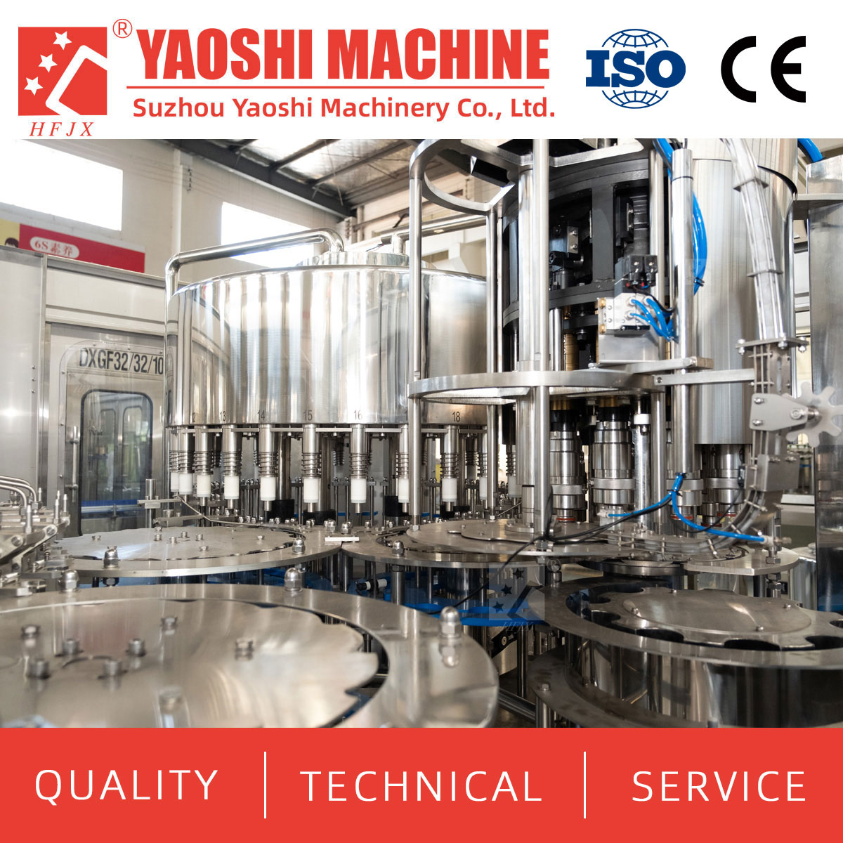
A water-filling monoblock should be selected from the real product, bottle and capacity conditions.
In a basic gravity arrangement, liquid flows from a product tank positioned above the filling point. The available liquid head drives water through the valve into the bottle. Air displaced from the bottle must leave through a defined path while filling continues to the designed stopping condition.
The actual machine may be rotary or linear, mechanical or electronically controlled, and integrated with bottle rinsing and capping. “Gravity” describes the product-delivery principle; it does not define the complete machine, automation level or acceptance method.
| Selection question | Gravity-filling implication |
|---|---|
| Does the liquid flow readily? | Low flow resistance supports gravity delivery, but temperature and additives must still be reviewed |
| Is the product non-carbonated? | Still water is a normal candidate; sparkling water requires a pressure-controlled review |
| Is the target a visible level or measured quantity? | The valve principle and bottle-volume variation determine how the result is controlled |
| Can displaced air leave consistently? | Bottle neck, vent path, filling speed and foam or aeration affect the cycle |
| Can product supply remain stable? | Tank level, inlet control and upstream pressure can affect repeatable flow |
State whether the product is purified water, mineral water, spring water, still drinking water, sparkling water or an enhanced water containing added ingredients. Do not classify a product only by the word “water.”
A gravity route is normally evaluated for non-carbonated water that flows readily at the intended filling temperature. If the product contains dissolved carbon dioxide that must remain in the package, the project needs a controlled pressure relationship between product and container. That is a different design problem from using gravity to fill still water.
Enhanced water may change foam, surface tension, sanitation, cleaning or product-contact compatibility. Provide the complete formulation information relevant to filling and representative product for testing when the water differs from a standard still-water product.
Water remains a low-viscosity liquid across normal filling conditions, but temperature can still affect dissolved gas release, condensation, bottle behavior and downstream labeling. State the minimum, normal and maximum filling temperatures.
If cold water creates external condensation, the label and code process may need additional review. If the product is warm or hot, confirm whether the bottle, closure, filler components and downstream handling are suitable. Gravity filling should not be selected from viscosity alone.
Some gravity valves are designed to create a controlled liquid level in the bottle. A consistent visible level can be commercially important, but identical levels do not always represent identical liquid quantities when internal bottle volume varies.
The buyer should state:
Declared bottle quantity
Target fill level and permitted visual variation
Minimum acceptable quantity
Overfill-control objective
Bottle internal-volume tolerance
Inspection and sampling method
If the project is primarily quantity-led or bottle-volume variation is significant, compare gravity level filling with flowmeter, volumetric, net-weight or another measurable-dose approach. The final choice should follow testing and the applicable product-control requirement.
Water can enter only as displaced air leaves. Bottle opening, neck finish, valve geometry and vent path affect filling time and stability. Provide a dimensioned bottle drawing and approved sample instead of stating only the nominal volume.
| Bottle input | Why it matters |
|---|---|
| Neck finish and opening | Define valve contact, centering, venting and closure compatibility |
| Height and diameter | Affect machine pitch, guides, star wheels and conveyor stability |
| Internal volume | Affects quantity when the machine fills to a level |
| Base and body stiffness | Influence support, transfer and behavior during filling |
| Dimensional tolerances | Help assess repeatable handling and fill presentation |
Test the smallest neck opening, the least stable bottle and the bottle with the greatest relevant tolerance. A machine that fills one standard sample correctly may not represent the full commercial bottle population.
PET bottles may be lightweight and flexible. Confirm neck handling, body stability, bottle support and deformation risk at the selected fill condition. Bottle quality from inline blowing or an external supplier should be included in the filling trial.
Glass bottles are heavier and rigid but require controlled transfers and a breakage-response plan. The supplier should review bottle support, centering, infeed, discharge and isolation after breakage. Container material does not by itself select the filling principle, but it changes how the machine presents and removes each bottle.
Do not extend a small-bottle gravity-filler specification to large containers without review. A large bottle has a longer fill cycle, greater filled weight, different neck handling and different capping and conveying requirements.
Returnable large bottles may also require external washing, internal washing, inspection and sanitizing before filling. The buyer should define whether the proposed machine handles single-use small bottles, larger PET containers or returnable water-cooler bottles.
Gravity filling depends on controlled product availability at the filler. The project should define the treated-water tank, transfer pump, pipework, inlet valve, filler-bowl level control, return path and sanitation boundary.
Ask the supplier to state:
Required water flow at stable and peak operation
Pressure and temperature at the machine connection
Product-tank operating condition
Level-control and refill response
Behavior during upstream interruption
Product drain, recovery and cleaning routes
A fluctuating tank level or inconsistent inlet supply can change the flow through a gravity-based system. The water treatment system and filling suppliers should agree the connection rather than leaving each side to assume the other provides stable conditions.
A pressure gravity filling machine may use a controlled pressure above the product to support or stabilize delivery, while the bottle remains near atmospheric pressure. However, terminology varies between manufacturers.

Machine layout and automation level are separate decisions from the liquid-filling principle.
Do not confuse pressure-gravity filling for still liquids with isobaric or counter-pressure filling for carbonated water. In a counter-pressure process, the bottle is pressurized as part of maintaining carbonation and controlling product transfer.
| Supplier term | Questions to ask |
|---|---|
| Gravity | What drives product flow, how does air leave, and what stops the fill? |
| Pressure-gravity or micro-pressure | Which space is pressurized, at what operating condition, and why is pressure used? |
| Overflow or vacuum-assisted | Is product returned, how is level controlled, and what bottle rigidity is required? |
| Flowmeter or volumetric | How is dose measured, calibrated and verified? |
| Isobaric or counter-pressure | How is the bottle pressurized and carbonation protected? |
Request a functional description, process diagram and valve sequence. The commercial name alone is not enough for technical comparison.
A 3-in-1 water filling machine normally integrates bottle rinsing, filling and capping in one monoblock. This reduces transfers between the three operations, but the filler still needs a defined operating principle and product duty.
Confirm the scope of each section:
Bottle infeed and transfer to rinsing
Rinsing medium, contact and drainage
Filling valve principle and product supply
Cap storage, sorting, feeding and application
Fill-level and closure inspection
Discharge conveyor and downstream signals
Cleaning, sanitation and drain connections
Two 3-in-1 machines can have different valve designs, bottle formats, automation scope and acceptance conditions. Compare the technical schedule, not only the number of combined functions.
Target BPH must be tied to bottle volume, neck, fill level and stable operating condition. Larger bottles require more liquid per cycle. A narrow vent path or slow air release can also limit filling speed.
The capacity schedule should distinguish:
| Capacity value | Definition required |
|---|---|
| Nominal speed | Reference bottle and machine condition used for the rating |
| Stable filler output | Agreed commercial bottle and continuous operating condition |
| Good bottle output | Accepted bottles at a named point after stated checks |
| Complete-line output | Accepted labeled or packed products at the agreed project boundary |
Do not assume the same BPH for every bottle size. Ask for a capacity basis and change parts for each planned SKU.
The filler may be able to run faster than the labeling machine or packaging machine can accept. Convert bottle output into labels, packs and pallets per hour. Review cap replenishment, label change, pack-material replenishment, pallet exchange and the usable conveyor accumulation between machines.

Stable packaged output depends on matching the filler with downstream equipment and usable accumulation.
A short buffer can absorb a temporary downstream stop. It cannot compensate for a downstream machine whose stable capacity is below the filler’s output. For a replacement project, collect blocked and starved time from the current filler before purchasing a faster monoblock.
A simple filling principle does not remove the need for a hygienic process. Define product-contact materials, internal surface requirements, tank and pipe drainage, cleaning method, sanitation sequence and separation from non-product utilities.
The supplier should identify which paths are cleaned automatically, which need manual intervention and how cleaning completion is verified. If the plant runs more than one product, include product-change and allergen or ingredient considerations where applicable.
Rinsing water, product water, cleaning water and drain streams should have clear connections. A gravity filler should be evaluated as part of the full treated-water and sanitation boundary.
| Project condition | Gravity route | Alternative to review |
|---|---|---|
| Still, readily flowing water | Strong candidate when bottle and output conditions are suitable | Flowmeter or another dose-control method if quantity control drives the project |
| Sparkling water | Normally not the same open gravity duty | Isobaric or counter-pressure process |
| Significant bottle-volume variation | Level may remain visually consistent while quantity varies | Measured-dose or weight-based comparison |
| Persistent foam or aeration | May reduce stable speed or presentation quality | Controlled-entry, vacuum-assisted or another tested approach |
| Large fill volume | Longer cycle may change machine size and economics | Alternative valve, multiple-stage flow or another machine family |
This is a shortlist, not a final rule. Representative product and bottle trials should confirm the selected method.
When replacing the main monoblock, record the existing infeed and discharge elevations, line direction, bottle pitch, cap-feed location, product connection, drains, electrical supply, PLC signals, safety circuits and available floor space.
Confirm which conveyors, cap systems, inspection devices and utilities remain. A machine that fits the footprint may still require new transfers, field pipework, control changes or additional accumulation.
The shutdown plan should include removal, rigging, installation, utility connection, dry testing, water testing and production ramp-up. Assign responsibility for every interface before the old equipment is disconnected.
| RFQ section | Information to provide |
|---|---|
| Product | Water type, carbonation, ingredients, temperature and quality requirements |
| Bottle | Material, drawing, neck, internal volume, tolerances and approved samples |
| Fill target | Declared quantity, visible level, headspace and inspection method |
| Output | Stable good BPH for each bottle and shift plan |
| Upstream | Water supply, tank, pump, pressure, temperature and cleaning boundary |
| Downstream | Cap, conveyor, inspection, labeling and packaging interfaces |
| Project scope | Standalone filler, 3-in-1 monoblock or wider connected line |
| Acceptance | Test materials, formats, duration, good-output point and quality checks |
Ask the supplier to explain why the proposed filling principle matches these conditions. A proposal that states only model, valve count and maximum BPH is incomplete.
Factory acceptance testing should use representative water, bottles and caps where practical. Test the most difficult normal format, start-up, stable operation, controlled stop, restart, no-bottle conditions, product-supply interruption and changeover functions.
Record output, fill result, closure quality, rejects and open items. Site acceptance should confirm the actual treated-water connection, conveyors, downstream signals, utilities and connected-line output.
If test conditions differ from production conditions, document the difference and the later verification method instead of treating a short dry run as proof of the complete duty.
Choosing the filling principle only because the product is called water
Using “pressure filling” without defining which space is pressurized
Confusing a 3-in-1 configuration with a filling principle
Specifying bottle volume without neck and tolerance drawings
Treating a consistent fill level as guaranteed identical quantity
Applying one BPH value to every bottle size
Ignoring tank level, inlet flow and product-supply stability
Buying a faster filler without checking downstream capacity
Leaving cleaning, drains and sanitation outside the specification
Accepting a quotation without a functional valve description
No. It is a normal candidate for still, readily flowing water, but carbonation, additives, temperature, fill target, bottle and output must be reviewed.
Not necessarily. Supplier terminology varies. Ask whether the product tank, bottle or both are pressurized and how the valve operates.
It can provide a controlled result under its designed conditions, but the buyer must define whether acceptance concerns visible level, measured quantity or both. Bottle-volume variation also matters.
Selected formats may share equipment when supports, transfers, necks, valves and closures are compatible. Each bottle still needs trial and a defined changeover scope.
No. Three-in-one describes the integration of rinsing, filling and capping. The filling principle must be stated separately.
Yaos Machinery supplies water filling and related beverage-line equipment. Prepare the water specification, bottle and cap files, fill target, output by SKU, upstream water conditions, downstream equipment and acceptance requirements. Request a proposal that explains the selected valve, product and air paths, operating pressure, capacity basis and complete monoblock scope.


+86-512-58530618

Wukesong Road, Sanxing Town, Zhangjiagang City, Jiangsu Province, China


