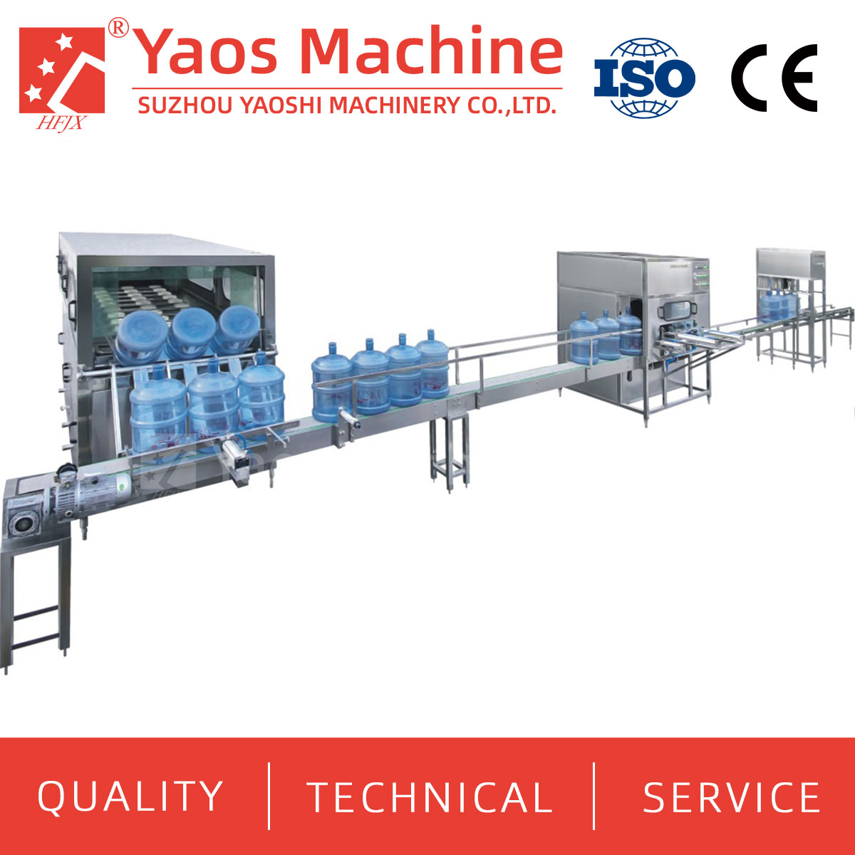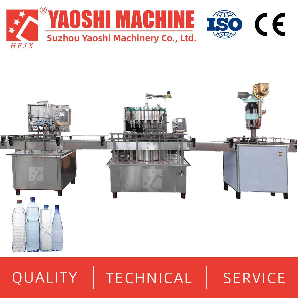
Rotary and linear water filling machines encounter recurring operational issues that reduce line efficiency and product quality. Understanding the root cause of each fault and applying the correct corrective sequence minimizes downtime and prevents repeat failures. This guide covers the most frequent problems observed in high-speed water filling lines.

Uneven fill levels between bottles on the same filler indicate one or more malfunctioning filling valves. The fault typically appears as a standard deviation exceeding ±3 mL on a 500 mL nominal fill.
Check the valve diaphragm or seal for wear. Replace any valve where the rubber seat shows cracking or permanent deformation.
Verify that the fill height probe is set at identical height across all valves. A 1 mm difference in probe position changes fill volume by 3 to 5 mL.
Inspect the product supply tank pressure. Fluctuations above 0.2 bar cause inconsistent flow rates across the valve circle.
Clean the valve vent tube with compressed air. Blocked vents prevent proper atmospheric balancing and cause slow fill cut-off.
Run a fill weight check on all stations. Record the results and replace any valve deviating more than 2 sigma from the mean.
Excessive foam at the end of the filling cycle leads to underfills and spillage on the capping turret. Foaming is most common in high-speed gravity fillers operating above 300 bottles per minute.
Reduce the product flow rate by adjusting the tank level. Lower head pressure decreases the velocity of liquid entering the bottle.
Verify that the bottle is fully seated on the valve seal. A misaligned bottle draws air into the product stream.
Inspect the vent tube position. The tube should terminate 5 to 10 mm above the final fill height to allow trapped air to escape.
Check product temperature. Water above 25 °C releases dissolved gases more readily and increases foam generation.
Ensure the conveyor back-pressure is not excessive. High back-pressure tilts bottles and breaks the valve seal.
Unstable bottles falling over after filling disrupts production flow and causes spillage. PET bottles with thin walls or non-standard base geometry are most susceptible.
Adjust the conveyor speed to match the filler discharge rate. Mismatched speeds create bottle accumulation zones.
Install side gripper belts at the filler exit. Holding bottles upright for the first 2 meters after filling stabilizes the containers.
Reduce the fill temperature if possible. Colder water stiffens PET side walls.
Check that the bottle base diameter matches the conveyor chain pitch. Narrow bases require guide rail spacing under 5 mm wider than the bottle.
Add starwheel infeed at the capper entry point. This prevents bottles from stopping abruptly and tipping.

Leaking caps after application cause product loss and customer complaints. The defect is often intermittent and hard to diagnose on a running line.
Verify the capping head torque setting. PET bottle caps require 1.5 to 2.5 Nm of applied torque. Values below 1.5 Nm will not form a liquid-tight seal.
Inspect the cap sorter for jammed or deformed caps. Caps that are oval after sorting cannot thread correctly.
Check the bottle neck finish for burrs or flash. Sharp edges cut into the cap liner and create leak paths.
Measure the headspace between the fill level and the cap. Less than 10 mm of headspace allows liquid contact with the cap liner, which softens the seal.
Test capping head alignment once per shift. Off-center heads apply uneven pressure and produce leakers on one side of the cap.
The no-bottle-no-fill system stops the filler when bottles are missing, but false trips reduce throughput.
Clean the optical sensor lenses. Condensation from the filling environment is a common cause of false readings.
Check the sensor mounting bracket for vibration-induced movement. Tighten and lock all adjustment screws.
Verify the bottle detection timing window. A window set too narrow trips on normal conveyor speed variations.
Inspect the starwheel pocket condition. Worn pockets allow bottles to sit off-center and miss the sensor beam.
Test sensor response with a known good bottle. Replace any sensor that fails bench testing.
Mechanical vibrations accelerate wear on bearings and seals. Routine monitoring prevents unexpected breakdowns.
Bolt down all machine feet to the factory floor. Machines not anchored within 3 mm of level will walk during operation.
Check the main drive belt tension. A loose belt causes chatter at the indexing cam input.
Inspect rotary bearing housings for wear. Vibration amplitude above 5 mm per second at the bearing cap indicates imminent failure.
Balance the filling carousel if vibration is synchronized with rotation. Even a 100 gram imbalance on a 36-station filler creates measurable instability at 400 rpm.
Replace worn timing belt pulleys. Pulley tooth wear increases backlash and generates periodic vibration.
How often should filling valves be serviced on a water line?
Standard preventive maintenance intervals are 2000 operating hours or every six months for valve seal replacement. High-speed lines running above 400 bottles per minute may need service at 1000 hour intervals. Keep a log of valve performance between service cycles.
Can fill volume drift occur due to ambient temperature changes?
Fill volume changes by approximately 0.2 percent per degree Celsius of water temperature variation. A closed-loop volume control system with real-time flow compensation reduces this drift. Without compensation, a 5 °C swing changes fill volume by 10 mL on a 500 mL fill.
What is the most common cause of fill valve clogging in water lines?
Scale deposits from hard water and particulate sediment from the supply tank are the primary clogging sources. Installing a 50-micron inline filter before the filler reduces clog frequency by 60 to 80 percent. Weekly back-flushing of the valve block prevents buildup.
Does bottle shape affect the filler's ability to handle different containers?
Bottles with asymmetrical shapes or off-center necks require longer changeover times and specialized handling stars. Round and square bottles are the most filler-friendly geometries. Bottles with handles or irregular profiles add handling complexity at the infeed and discharge stars.
Is it advisable to run the filler at reduced speed to solve multiple issues at once?
Reducing speed by 10 to 15 percent often resolves foaming, toppling, and fill accuracy issues simultaneously. This is a valid short-term corrective action while planning permanent repairs. Running below 60 percent of rated speed may cause timing problems in the downstream capper and labeller.
Most water filling machine problems share common root causes related to valve condition, bottle alignment, and conveyor synchronization. A structured troubleshooting approach that follows a sequence of checks from simplest to most complex resolves the majority of issues within one shift.
For plant operators seeking reliable filling equipment with documented service protocols, Suzhou Yaoshi Machinery Co., Ltd., under its brand hfjx machine, manufactures CE-certified rotary and linear fillers designed for rapid maintenance access. The company's Zhangjiagang factory produces filling systems with standard valve service kits and diagnostic ports for real-time fault monitoring.


+86-512-58530618

Wukesong Road, Sanxing Town, Zhangjiagang City, Jiangsu Province, China