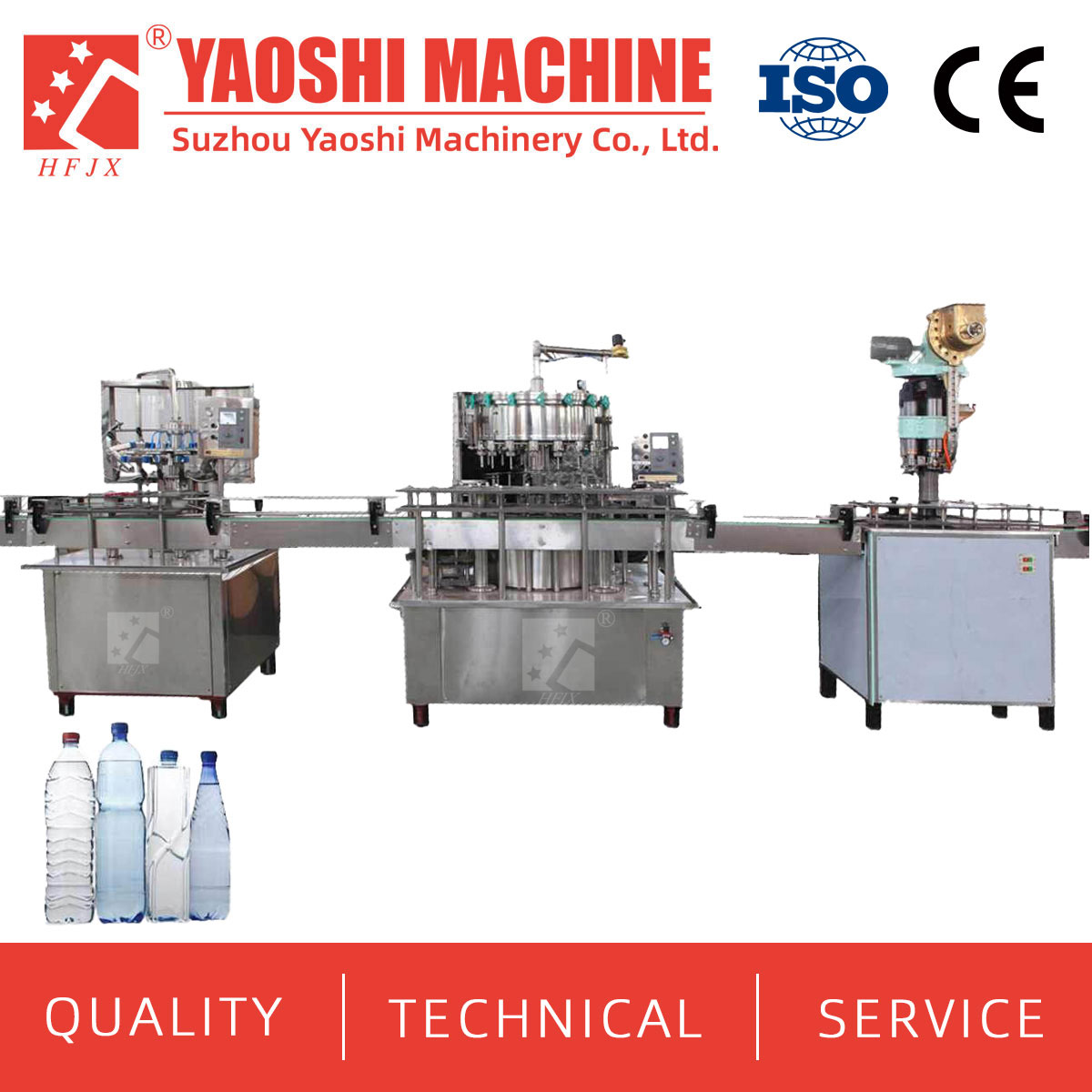
A mineral water bottling line can contain machines with suitable individual speed ratings and still fail to reach the required finished-pack output. The cause is often found between the machines: unstable bottle transfer, incompatible conveyor heights, wet bottles at the labeler, a packer rate based on the wrong pack pattern, or controls that do not exchange line-status signals.
Interface planning connects each module to the same bottle, capacity and operating basis. This guide covers the mechanical, process, electrical and speed information a buyer should confirm before requesting a coordinated line quotation.
The first engineering document should identify what crosses every module boundary. A bottle is only one part of the transfer. Water, caps, labels, film, signals, utilities, rejects and operating responsibility also move through the line.
| Interface | Information entering the interface | Supplier must define | Risk if left open |
|---|---|---|---|
| Blower to filler | Bottle drawing, neck finish, bottle condition, discharge rate and transfer method | Air conveyor or bottle conveyor, elevations, guide parts, controls and accumulation | Bottle deformation, jams, scuffing or filler starvation |
| Water system to filler | Treated-water quality, flow, pressure, temperature and sanitation basis | Tank, pump, pipe size, valve boundary, instruments and connection point | Unstable supply or an incomplete hygienic boundary |
| Filler to labeler | Filled-bottle rate, discharge height, bottle spacing, surface condition and code location | Conveyor, inspection, drying, bottle separation, reject handling and buffer | Poor label application or repeated short stops |
| Labeler to packer | Labeled-bottle rate, pack pattern, film or carton and label acceptance criteria | Lane formation, pack infeed, inspection, accumulation and discharge format | Incorrect pack conversion or downstream restriction |
| Controls and safety | Operating modes, machine states, line speed reference and stop conditions | Signal list, control ownership, emergency-stop zones and restart sequence | Machines stop independently or restart without a coordinated sequence |
Every speed in the quotation should refer to a named SKU. Record the bottle volume, dimensions, bottle material, cap, label and final pack. State the required bottles per hour for each format, plus operating hours, planned changeovers and the daily quantity of accepted packs.
Separate the filler’s rated capacity from the expected stable line output. The supplier should state the bottle and pack assumptions behind both. For a shrink-wrapped pack, convert the packer rating into bottles per minute using the required bottles per pack. Repeat the calculation for every main pack pattern. A machine listed in bags per minute cannot be balanced against a filler listed in BPH until this conversion is made.
Avoid applying one unexplained overspeed percentage to every module. The required margin depends on stop frequency, restart behavior, product accumulation, changeovers and the role of each machine. Ask the line supplier to show the design rate, expected operating rate and buffer logic for each section.
If bottles are made on site, the PET blow molding machine and filler must share the same approved bottle definition. Submit the preform, bottle and neck-finish drawings, target bottle weight, mold information and production samples when available. Confirm every SKU that will use the transfer system.
The mechanical interface includes blower discharge height, bottle orientation, transfer direction, conveyor type, neck-guide details and filler infeed elevation. The bottle should arrive in a condition that the transfer and filler can handle consistently. Ask the supplier to define the route from the blower discharge to the filling monoblock, including bends, elevation changes, access points and the response to a downstream stop.
Preform and bottle drawings for each format
Neck finish, bottle height, diameter, weight and base design
Required bottle rate and the operating basis for that rate
Blower discharge direction, height and control signals
Air-conveyor arrangement, filtration requirements and available air
Accumulation or controlled-stop strategy
When empty bottles are purchased, replace the blowing interface with bottle storage, unscrambling and infeed requirements. State how bottles arrive at the plant, how they are protected and how they will be presented to the filler.
The product-water interface needs a process basis as well as a pipe connection. Provide the raw-water report, selected treatment concept, finished-water target, required filler flow and cleaning plan. The line supplier should define the finished-water tank, transfer pump, pressure or level-control arrangement, pipe route, connection size, instruments and sanitation boundary.
Tank capacity and pump duty should reflect filler demand and the way the treatment system operates. The quotation should identify which supplier provides the tank, pump, valves, instruments, interconnecting pipework and controls. It should also state how low water availability is communicated to the filler and how the system behaves during a line stop.
Yaoshi Machinery’s water filling machine range includes integrated rinsing, filling and capping equipment. The named CXGF product page shows a process sequence from bottle blowing or unscrambling through air conveying, rinsing, filling, capping, inspection, drying, coding, labeling and packing. That sequence is useful for locating interfaces, but every project still needs a bottle-specific layout and line balance.

| Model | Published capacity | Rinsing / filling / capping heads | Published size | Published power | Published weight |
|---|---|---|---|---|---|
| CXGF8-8-3 | 2,000 BPH | 8 / 8 / 3 | 2300 × 1500 × 2100 mm | 3.8 kW | 2,800 kg |
| CXGF24-24-8 | 8,000–12,000 BPH | 24 / 24 / 8 | 3100 × 2450 × 2300 mm | 5.2 kW | 6,500 kg |
| CXGF40-40-10 | 18,000–24,000 BPH | 40 / 40 / 10 | 4550 × 2650 × 2300 mm | 9.6 kW | 8,500 kg |
| CXGF60-60-15 | 28,000–36,000 BPH | 60 / 60 / 15 | 5450 × 3210 × 2300 mm | 12 kW | 12,000 kg |
The same published matrix lists a bottle-diameter range of 50–115 mm, bottle height of 160–320 mm and compressed-air pressure of 0.3–0.7 MPa. These figures apply to the listed product matrix. Submit actual bottle and cap drawings to confirm guides, star wheels, gripping points, cap handling and change parts.
The filler quotation should also state infeed and discharge elevations, conveyor direction, cap-supply point, rejected-bottle handling, operator access, maintenance clearance and signals exchanged with upstream and downstream machines.
A filled bottle may leave the capper wet, closely spaced and moving at a variable rate during stops and restarts. The labeling section must receive bottles at the spacing and surface condition required by the selected label process. Define whether inspection, bottle drying and date coding occur before or after label application.
Yaoshi Machinery lists OPP hot-melt, shrink-sleeve and self-adhesive equipment in its labeling machine range. Selection depends on the approved bottle and label rather than bottle volume alone. Submit the bottle drawing and sample, label material, roll or sleeve dimensions, application position, artwork reference, direction of feed and acceptance criteria.

The interface schedule should record conveyor height and width, bottle pitch, normal and short-term rate, bottle condition, labeler infeed method, reject position and permitted accumulation. For multiple SKUs, request a change-part list and identify which settings are recipe controlled and which require manual adjustment.
The packer needs an approved secondary-pack specification. State the number and arrangement of bottles, film or carton material, tray requirement, handle requirement, print orientation and finished-pack discharge direction. The bottle rate must be converted into packs per minute for each SKU.
The packaging machine range includes downstream equipment for beverage containers. One published WP-350A film shrink-wrapper specification lists 16–20 bags per minute, an overall size of 12000 × 1100 × 2100 mm, equipment power of 30 kW, weight of 2,500 kg and air pressure of 0.6–0.8 MPa.

| WP-350A published item | Published value | Interface question for the buyer |
|---|---|---|
| Production capacity | 16–20 bags/minute | How many bottles are in each pack, and what bottle rate does that represent? |
| Maximum package size | 2400 × 650 × 450 mm | Does the approved pack drawing fit the stated envelope? |
| PE film thickness | 0.03–0.15 mm | Which production-intent film will be used for testing? |
| Overall size | 12000 × 1100 × 2100 mm | Is there enough room for infeed, discharge and maintenance access? |
| Equipment power | 30 kW | Does the utility schedule use the selected voltage and full line load? |
| Air pressure | 0.6–0.8 MPa | Can the plant supply the required pressure at the connection during peak demand? |
The published rate is a machine parameter, not confirmation that a particular bottle and pack pattern will match the filler. Request a pack trial basis and a line-balance calculation using the same SKU. Include accumulation before the packer where the proposed operating logic requires it.
Each machine should exchange defined ready, running, fault, blocked and starved states with the line controller or neighboring equipment. The controls document should show which machine supplies the speed reference, how conveyors respond to accumulation and what happens after an emergency stop or material shortage.
Ask for an interface signal list, operating-mode description, alarm ownership and restart sequence. Confirm the electrical standard, control voltage, network or hardwired interface, cabinet locations and cable-supply boundary. Emergency-stop zones and guarding interfaces should be reviewed against the final layout and the buyer’s site requirements.
Utility interlocks also belong in this schedule. Loss of treated water, compressed air, cooling or packaging material should produce an agreed response without creating uncontrolled bottle accumulation.
Conveyors set bottle pitch, direction, elevation and accumulation behavior between machines. Provide the building plan with columns, walls, doors, drains, ceiling heights and operator routes. The supplier should return conveyor widths, elevations, transfer details, motor locations, access points and the usable accumulation available in each section.
Buffer length should be based on the likely stop and recovery behavior of the connected machines. A longer conveyor does not automatically create useful accumulation, especially if bottles cannot remain stable or if the controls release them poorly. Ask the supplier to explain which short stops a buffer is intended to absorb and how the line clears after restart.
A coordinated quotation should include an interface register rather than separate machine brochures. For each boundary, identify the design owner, equipment supplier, installation party, connection point, required input, output condition and acceptance document.
| RFQ file | Information to include | Expected supplier return |
|---|---|---|
| Water and process file | Raw-water report, finished-water target, required flow and sanitation basis | Process flow, tanks, pumps, pipe boundary and utility demand |
| Container file | Preform, bottle, neck and cap drawings; samples; SKU list | Compatibility review, change parts and transfer concept |
| Capacity file | BPH by SKU, shifts, changeovers, pack patterns and daily output | Module speed table, assumptions and accumulation plan |
| Label and pack file | Label specification, code position, film or carton and pack drawing | Labeling and packing selection, material requirements and trial basis |
| Site file | Dimensioned layout, access, utilities, drainage and floor information | Line layout, elevations, loads, clearances and connection schedule |
| Controls file | Electrical standard, operating modes and required plant interface | Signal list, control boundary, alarm ownership and restart logic |
The ratings should first be checked against the same bottle. The line supplier should then define the operating rates, stop behavior and accumulation strategy rather than matching two headline figures alone.
Provide bottle material, weight, height, diameter, neck finish, base design, controlled drawing and sample. Include the preform and mold information when bottle blowing is part of the project.
The required surface condition depends on the label process and approved materials. Confirm the bottle condition at the labeling point and place drying or inspection equipment accordingly.
Convert packs per minute into bottles per minute using the approved pack pattern. Compare that result with the line rate for the same bottle, then include the proposed operating margin and buffer logic.
Compatibility depends on bottle geometry, label material, application position and speed. Submit every format and request a change-part list, setting range and trial plan.
The final list is project specific, but it normally needs to communicate availability, running state, faults, upstream blockage and downstream starvation. The supplier should document signal ownership and restart behavior.
There is no useful universal length. It should follow bottle stability, line layout, machine stop patterns, recovery time and the stops the buffer is intended to absorb.
Request the equipment list, bottle and pack basis, module speed table, layout, interface register, utility schedule, change parts, control description and an included, optional and excluded scope table.
Send Yaoshi Machinery your raw-water report, bottle and cap drawings, required BPH for each bottle size, label and final-pack specifications, factory plan and available utility conditions. Ask for a bottle-specific equipment list, line layout, speed-balance table, conveyor and buffer plan, interface register and utility schedule.
Email tony@yaos.ltd or call +86 18915689808. Identify purchased bottles or in-house blowing and mark every unconfirmed SKU or site condition so the quotation can state its assumptions.
<!--!doctype-->


+86-512-58530618

Wukesong Road, Sanxing Town, Zhangjiagang City, Jiangsu Province, China