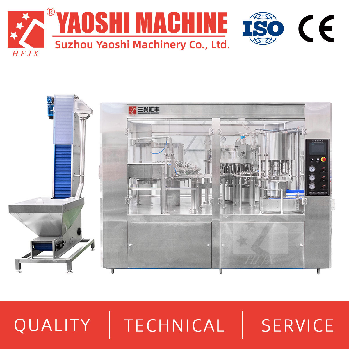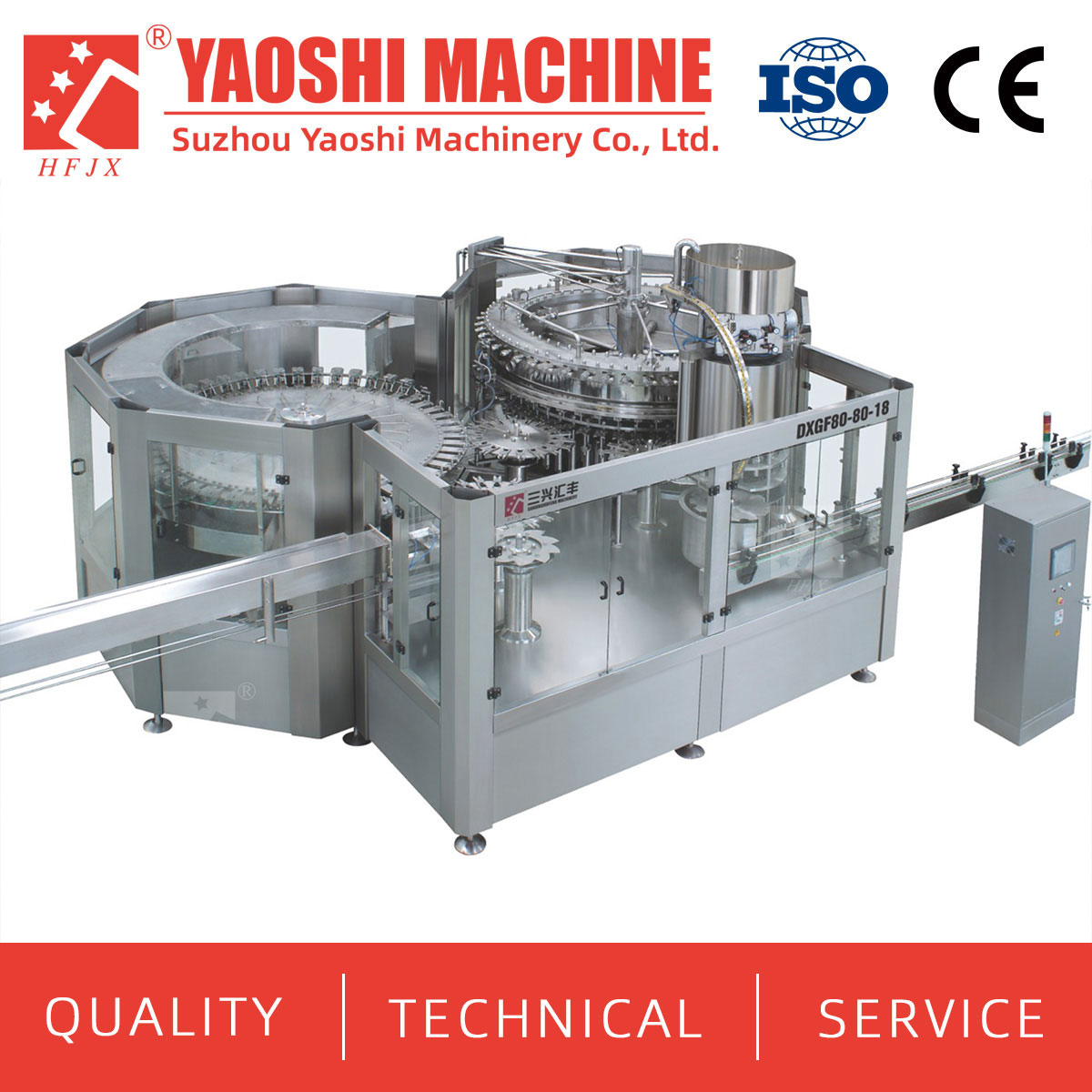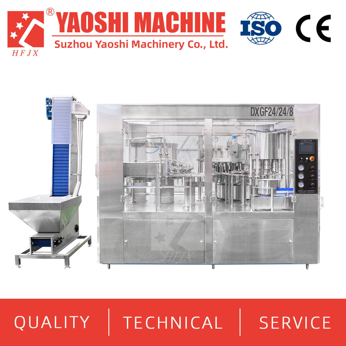
An aseptic carbonated drink filling machine must receive product through a process that preserves its required microbiological condition while maintaining the agreed carbonation and filling conditions. Connecting a sterilizer, carbonator and pressure filler does not by itself establish an aseptic system. Every product, gas, container and closure entry needs a defined treatment and transfer boundary.
For the application discussed here, Yaoshi Machinery's scope covers sterile transfer and aseptic filling and capping. Product sterilization and carbonation require separately confirmed equipment and responsibility assignments. Start the technical review with an interface drawing that shows how those upstream duties connect to the filling section.
Product sterilization addresses the microbiological requirements of the beverage. Carbonation establishes its dissolved CO₂ condition. Pressure filling manages the transfer of carbonated product into the package. These duties are related, but one does not replace another.
In particular, pressure control and an enclosed filler do not establish aseptic performance. The product route, gas supply, package treatment and filling environment need a documented design and verification basis. For your carbonated drink filling machine inquiry, state the intended preservation process as well as the carbonation target.
Do not select a sterilization schedule from the machine catalogue. The product formulation, required shelf-life conditions and process-validation requirements should be defined with the responsible process and quality specialists. Our engineering team needs those approved requirements to review the transfer and filling interfaces.
One integration route to evaluate is product treatment, cooling to the agreed carbonation condition, carbonation under the required microbiological controls, then sterile transfer to filling and capping. This is a planning sequence, not a universal process prescription.
The approved process must determine where carbonation occurs. If CO₂ is introduced after product sterilization, the carbonator and gas supply become part of the protected product route. If a different sequence is proposed, the process owner must establish how the treatment and carbonation requirements are both met.
Supply a flow diagram for the complete beverage preparation route, including ingredient additions, cooling, any intermediate vessels and the proposed carbonation point. Identify every addition downstream of the product-treatment step. A connection described only as “sterile product inlet” leaves too much undefined.
Use our carbonated soft drink line solution as an equipment-planning reference, then identify the separate aseptic requirements in the project specification. A conventional line layout is not evidence of an approved aseptic process.
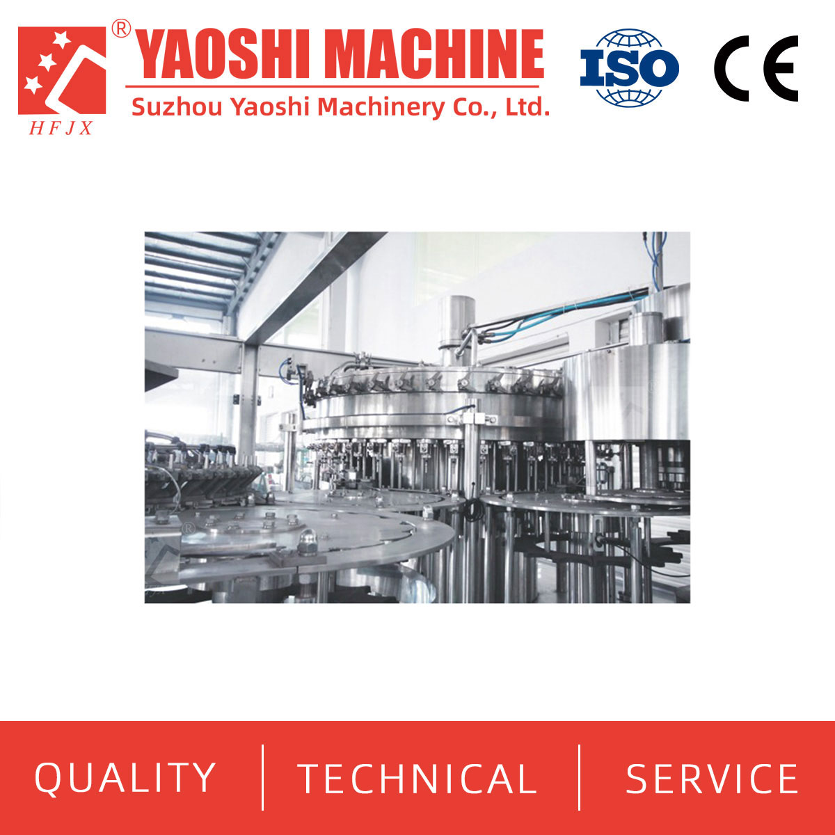
Conventional CSD equipment imagery from our product materials, shown for equipment orientation only. It does not depict or verify the proposed aseptic configuration.
The scope matrix should name an equipment owner and an interface owner. “By others” is incomplete unless the receiving conditions, documents and verification duties are also assigned.
| Process duty | Responsibility for this project | Interface to define |
|---|---|---|
| Product sterilization and any downstream cooling | Supplier and process-validation owner to be identified separately | Approved product condition, flow, pressure and release criteria at handover |
| Carbonation | Carbonator supplier and integration responsibility to be confirmed | CO₂ target, temperature, pressure, flow range and protection of the treated product |
| CO₂ supply and treatment | Gas supplier, treatment-equipment owner and verification responsibility to be assigned | Required gas quality, treatment method and connection to the protected route |
| Sterile product transfer | Yaoshi Machinery scope, within agreed connection limits | Piping and valve boundaries, utility interfaces and maintenance of the required condition |
| Container and closure treatment and delivery | Equipment and responsibility to be confirmed explicitly | Approved treatment, protected transfer and handover to filling and capping |
| Aseptic filling and capping | Yaoshi Machinery scope for the approved application | Accepted package, product-inlet conditions, output and verification obligations |
Package treatment deserves its own line. Confirming aseptic filling and capping does not automatically define who supplies bottle or cap treatment equipment. The method, supplier and protected handover must be agreed before the complete sterile boundary can be assessed.
The same discipline applies to upstream beverage preparation equipment. Listing a preparation module does not establish its suitability for the specified sterile duty. Identify the exact function and the evidence required at its outlet.
Send the recipe characteristics relevant to processing and filling, including viscosity, solids or particles, foaming behavior and any ingredients added after treatment. Provide the target CO₂ content with its units, sampling point and measurement method.
Define temperature, pressure and flow at the agreed filling-section inlet. Include the permitted variation during normal production and the required response to interrupted demand. Avoid a single nominal value without an operating range or a statement of where it applies.
Pressure and temperature conditions influence carbonation behavior, so the carbonator and filling-section suppliers need a shared operating basis. Ask who controls the handover, which signals are exchanged and what happens when either section stops. Any intermediate storage must have a defined purpose and protection strategy; it should not be added simply to hide a speed mismatch.
Do not confuse factory compressed-air pressure with beverage filling pressure or a sterile-gas specification. Each utility and process connection needs its own defined duty in the interface schedule.
The published DXGF product table includes the following conventional CSD reference entries. They are provided to distinguish catalogue capacity from the separate specification needed for your aseptic application.
| Published DXGF reference | Listed capacity | Listed power | Aseptic-project status |
|---|---|---|---|
| DXGF18-18-6 | 3,000–5,000 BPH | 5.2 kW | Not an aseptic configuration or output specification |
| DXGF40-40-12 | 10,000–15,000 BPH | 7.5 kW | Not an aseptic configuration or output specification |
Source: our Carbonated Soft Drink (CSD) Filling Machine product specifications. Neither these capacity entries nor the power ratings establish the performance, utility demand or microbiological verification of an aseptic project. The offered sterile-transfer, filling and capping configuration requires its own approved technical sheet.
That sheet should state the package and closure, accepted output by format, product-inlet conditions, cleaning and sterilization provisions, required utilities and verification documents. Unsupported temperature, pressure, filter or cycle values should remain open technical items rather than becoming assumed specifications.
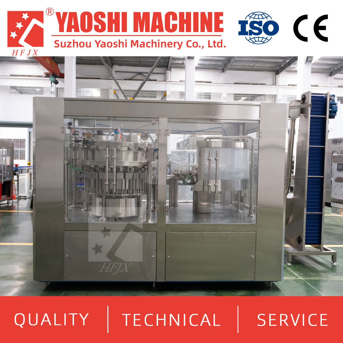
Conventional CSD monoblock illustration. An enclosure and cap feeder alone do not demonstrate an aseptic filling environment or sterile closure transfer.
A mechanical run and a microbiological verification answer different questions. Agree which factory tests establish handling, filling and closing functions, and which qualification activities establish the required aseptic performance of the connected route.
Request a documented plan covering cleaning, sterilization, release to production, relevant monitoring and the response to a loss of required conditions. Where CIP or SIP is specified, define its coverage and connection responsibilities. Cleaning alone should not be presented as proof of sterilization.
Agree who approves the protocol, performs the work, supplies materials and utilities, records results and authorizes production. If a microbiological challenge or media simulation is required, its design and acceptance criteria belong with the responsible specialists. Do not borrow another supplier's test result or a different product's process as validation for this line.
Review stops, sampling, interventions and restart conditions across the same boundary. Approval of individual machines is not, by itself, approval of their combined sterile route.
No. Isobaric filling describes a pressure-filling approach. Aseptic performance requires separate design, treatment, protection and verification of the relevant product and package routes.
The approved product process determines the sequence. Carbonation after sterilization requires the carbonator and gas connection to preserve the required product condition; an alternative sequence needs its own validated basis.
The scope discussed here covers sterile transfer and aseptic filling and capping. Product sterilization, carbonation and their supplier responsibilities must be confirmed separately in the project agreement.
No inclusion should be assumed. Define treatment equipment, protected transfer and connection limits explicitly, even when filling and capping are supplied together.
They can identify a conventional catalogue reference, but they cannot serve as aseptic performance data. Request a configuration-specific technical sheet and verification scope.
Do not make that decision from the filler description. The approved preservation process and complete system verification must establish the required treatment route.
To discuss an aseptic carbonated drink filling machine with Yaoshi Machinery, send container and closure drawings, the packaging format and target line speed. Add recipe characteristics, the proposed sterilization and carbonation sequence, inlet conditions and existing equipment interfaces. Contact tony@yaos.ltd or +86 18915689808 for a sterile-transfer, filling and capping scope review with the upstream responsibilities clearly identified.


+86-512-58530618

Wukesong Road, Sanxing Town, Zhangjiagang City, Jiangsu Province, China