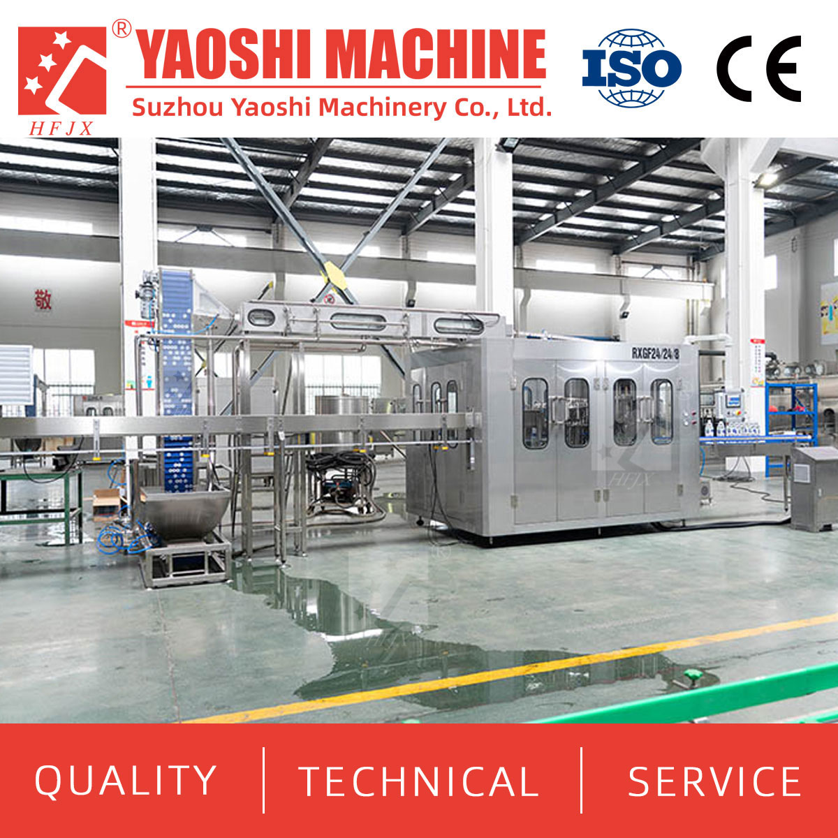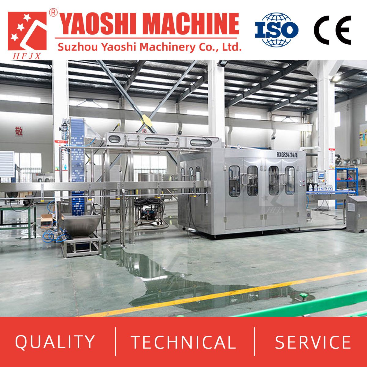
Specify a juice filling and capping machine around an approved bottle-and-closure combination. The bottle neck, cap, sealing feature, application method and production process must work together. Matching a nominal cap diameter is only the first check.
This guide focuses on the closure decision: what the package suppliers should confirm, what the capper needs to handle, and which interfaces must be defined before selecting equipment. It applies to new juice projects, bottle changes and filling or capping replacements. The exact recipe, filling process and required output remain part of the application review.
Send a dimensioned neck-finish drawing with the bottle drawing, cap drawing and production samples. Identify the finish designation, thread geometry, sealing surfaces, support features, tolerances and relevant tamper-evidence features. A cap and bottle carrying the same nominal diameter can still require a detailed compatibility review.
Ask the package suppliers to confirm the sealing arrangement: liner, gasket, bore seal or another specified design. Record the actual cap material and seal construction rather than assuming every screw cap uses a liner. Changes to these components should trigger a review of the approved package and machine setup.
Then ask Yaoshi's juice filling and capping equipment team to confirm the proposed application method, bottle handling, cap feeding and format parts against that package pair.
| Package Input | Information Needed | Supplier Decision |
|---|---|---|
| Bottle neck and finish | Dimensioned drawing, tolerances, sealing surface and samples | Compatibility with the cap, support and handling arrangement |
| Cap body | Drawing, material, outside shape, grip features and dimensions | Sorting, presentation and application tooling |
| Seal | Liner, gasket, bore seal or other approved construction | Application conditions and integrity checks |
| Tamper-evidence features | Band and matching bottle features; any tether geometry | Feeding clearance, application and opening behavior |
| Product process | Formula characteristics, filling conditions and post-fill cycle | Material suitability and tests after the full process |
Identify the closure family before discussing capper settings. A screw cap, lug closure, roll-on closure or press-on design requires an application and acceptance method appropriate to that package. Do not assume that one supplied capping system can run all these types.
For a screw-cap project, ask the closure supplier for its application specification and the machine supplier for the proposed control method. Confirm how the cap is gripped, how the bottle is supported, and which adjustments or parts are required. The offer should identify the actual design rather than describe it only as “adjustable capping.”
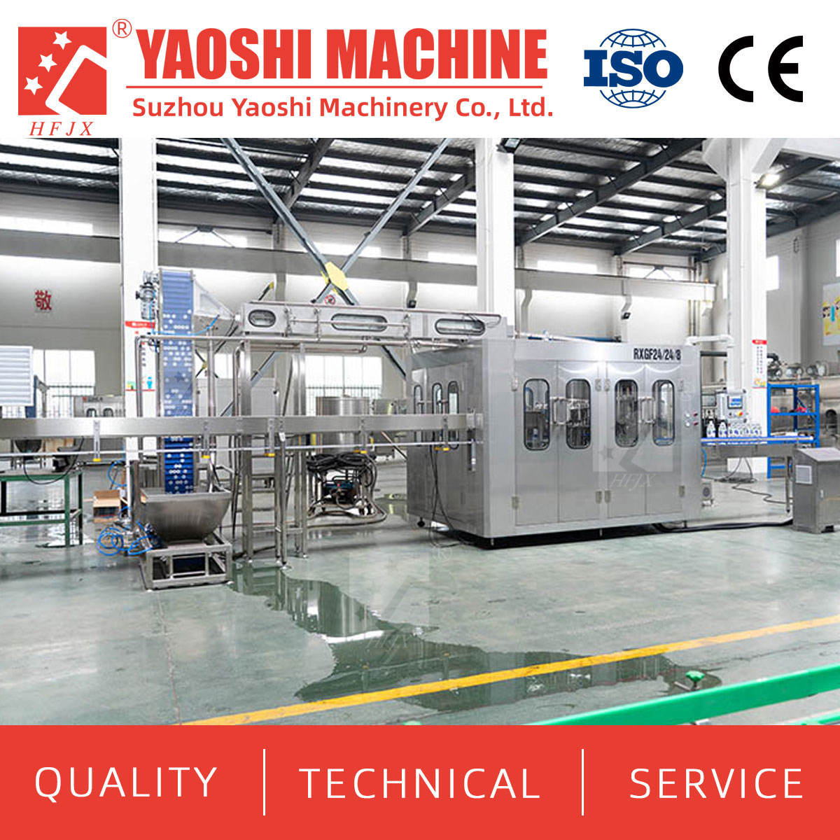
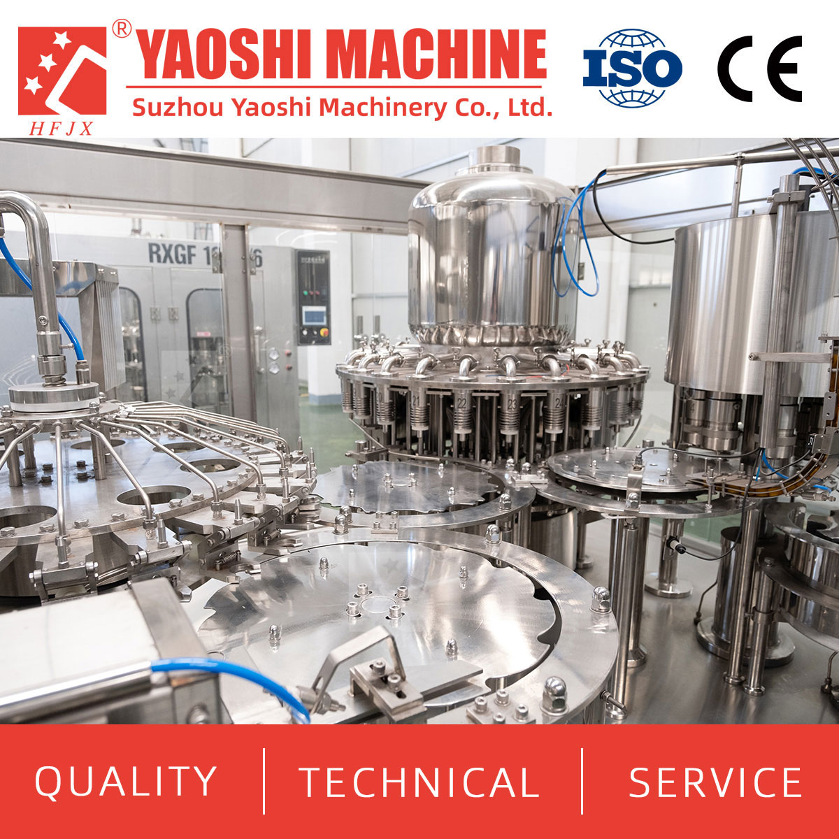
Official website equipment image. The visible cap feeder and enclosure illustrate an equipment arrangement; the approved closure type and tooling require project confirmation.
Application torque is the turning effort used to apply a threaded cap. Removal torque is measured when opening the applied closure later. They are related measurements, but a capper setting is not the same result as an opening test on a finished package.
For each approved bottle-cap pair, state the units, instrument, measurement method, sample conditioning, time after capping and acceptance range. Include measurements after the relevant cooling or other package process. Ask the closure and machine suppliers to agree how settings are established and verified; avoid copying a universal torque number or ratio from a generic chart.
Torque should be reviewed with seal integrity, cap position, thread condition, tamper-evidence behavior and acceptable opening. Increasing a setting is not a reliable substitute for investigating an unsuitable package or incorrect application.
Provide the formula characteristics and the approved or proposed filling route. For hot-fill, the cap, seal and neck must be assessed through filling, closing and cooling, including any hold or inversion required by the approved process. A package that appears acceptable immediately after capping still needs the agreed post-process checks.
For ultra-clean or aseptic projects, request the separate cap-treatment, protected-transfer and validation scope. A compatible closure and a capping machine do not establish that complete process. Yaoshi's juice process solution page can support the initial route discussion; the proposed configuration and evidence must be confirmed for the project.
Ask how the supplier will assess product splash or residue around the bottle finish before capping, particularly where foam or pulp is relevant. Agree the acceptance conditions and corrective design if trials identify a problem. Do not add a rinse or treatment step without reviewing its effect on the approved process.
The cap route includes storage and loading, sorting, orientation, transfer and presentation to the applying mechanism. Specify which functions the supplier includes and the condition in which caps must arrive. Ask for permitted cap variation and a test using intended production lots.
Review cap geometry, grip surface, tamper band and any tether or additional feature for interference during feeding. A closure change can affect the entire cap route, not just the final application head. Confirm how rejected or jammed caps are handled and whether they can be reintroduced under the approved procedure.
Ask what happens when cap supply becomes low or stops. Detection, alarms, machine response and recovery should be stated in the offer and demonstrated where included. Do not presume that every advertised control feature is fitted to the quoted machine.
For an integrated unit, request the relevant internal handoff conditions. For separate machines, add transfer height, conveyor direction, spacing, bottle support and available accumulation. Check how filled bottles remain stable and how the neck reaches the capping position.
The interface schedule should identify product or package conditions, required bottle rate and the agreed response to a capper stop. Name the party responsible for controls, upstream stop signals, restart and affected-bottle handling. For temperature-sensitive processes, the permitted delay between filling and closure must come from the approved process basis.
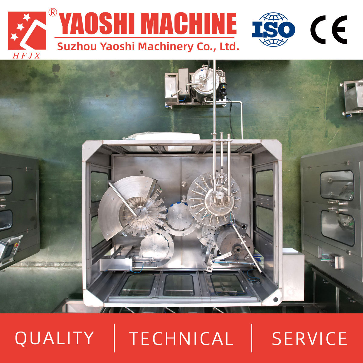
Official website top-view image. Use the supplier's drawings to confirm the actual transfer layout and change parts for each bottle.
List every launch bottle-cap combination. A change in bottle body with an unchanged neck can affect guides, support and transfer. A new cap can affect sorting, feeding and application tooling. The supplier should state which formats share parts, which require adjustments and which remain subject to trial.
For each SKU, name the accepted bottle output and relevant process conditions. Require a demonstrated changeover method for the included formats. Future bottle or closure designs should remain visible options until the supplier reviews their drawings and samples.
At the outlet, define the condition delivered to labeling equipment or another downstream machine. Include bottle stability, closure condition, rate and any required inspection or reject point.
The following values come from Yaoshi's published “Juice beverage hot filling machine” model table. They provide preliminary machine-size and capacity references. They do not specify a cap-size range, torque acceptance window, tooling or compatibility with a new closure.
| Published Model | Listed Capacity | Listed Power | Dimensions (mm) | Closure Data to Request Separately |
|---|---|---|---|---|
| RCGF18-18-6 | 8,000 BPH | 4.4 kW | 2800 × 2150 × 2500 | Approved bottle/cap pair, application mechanism, tooling and test limits |
| RCGF40-40-12 | 24,000 BPH | 7.8 kW | 4500 × 3300 × 2600 | Cap-feeding scope, format parts and sustained closure performance |
Request the reference product, bottle and test conditions behind each rate. Some public model ratings and bottle ranges differ between website tables, so use one signed datasheet for the offered build. Model codes and general catalogue descriptions should not replace an approved capper specification.
Use intended bottles, caps and product for tests that depend on filling conditions. A dry mechanical run can demonstrate selected motions, but it does not reproduce a filled package's closure performance after heating, cooling or storage.
| Test Area | Checks to Agree | Records Needed |
|---|---|---|
| Package compatibility | Cap seating, alignment, thread or seal condition and tamper features | Drawings, component lot references and sample results |
| Closure performance | Applicable torque or closing checks, integrity and opening behavior | Method, units, timing, conditioning and acceptance results |
| Production flow | Cap feeding, bottle transfer, accepted rate and rejects | Run duration, count point, stop events and defect definitions |
| Recovery and changeover | Cap shortage, jam response, restart and approved format changes | Sequence, supplied features, settings and open actions |
Agree sampling across the run and, where applicable, across capping positions. Identify any destructive tests and provide suitable samples for the remaining checks. Confirm which work is completed during factory acceptance testing and repeated at site.
Before ordering, obtain a package compatibility matrix, application specification, tooling list, cap-route drawing, interface schedule and test plan. The final quotation should name supplied inspection, rejection and control functions and allocate any buyer-side equipment.
No. Review the neck and closure drawings, sealing design, tolerances and actual samples as a pair.
Do not treat the measurements as interchangeable. Agree application conditions and separate removal-test requirements with the package and machine suppliers.
No. Excessive application can damage the package. Confirm a suitable range using the actual bottle, cap, seal and process.
It needs a handling review. Body geometry and stability can affect guides, support and transfer even when the closure remains unchanged.
Only if the supplier explicitly confirms the required application configurations and parts. Do not infer that capability from the machine category.
Confirm the package through filling, closure and the approved post-fill cycle. Set closure measurements at defined conditions and times.
The filled-bottle handoff: transfer geometry, spacing, stability and the response when the next machine stops.
Send formula characteristics, process, bottle and cap drawings or samples, required output, and existing interface information.
For a new juice line, package change or machine replacement, send Yaoshi Machinery your formula characteristics, process route, bottle and cap drawings, and target output. Add the closure supplier's application requirements and retained-equipment data where available. Request a compatibility matrix, tooling scope, interface schedule and package-test plan. Contact tony@yaos.ltd or +86 18915689808.
<!--!doctype-->


+86-512-58530618

Wukesong Road, Sanxing Town, Zhangjiagang City, Jiangsu Province, China