A machine list cannot tell you whether a new water factory will work inside a real building. The equipment may fit on the floor plan while a column blocks a service door, a drain sits on the wrong side of the filler, or forklifts cross the clean bottle route. These conflicts are expensive to correct after equipment drawings are approved.
A useful water factory equipment layout must coordinate the process, container route, people, packaging materials, utilities, drainage, maintenance and dispatch. This article treats small PET bottle lines and 3- or 5-gallon barrel lines separately because their container handling and factory flow are different.
Start with a measured building drawing rather than a rough room sketch. Show internal length and width, clear height, structural columns, beams, doors, floor levels, pits, existing drains, utility entries and immovable equipment. Mark the unloading route from the site entrance to each final machine position.
The drawing should also include operator access, guard-door clearance, control-panel access, component removal paths and lifting space. Machine footprints alone do not represent the working area required for operation and maintenance.
| Layout input | Required information | Decision supported |
|---|---|---|
| Building envelope | Internal dimensions, clear height, columns and fixed obstructions | Line direction and usable equipment area |
| Access | Door dimensions, unloading position, turning space and lifting method | Whether machines can reach their final positions |
| Floor | Levels, load limits, finish, pits and planned foundations | Equipment support and drainage coordination |
| Utilities | Source locations for power, air, water, cooling and drainage | Connection routes and utility-room placement |
| Logistics | Material receipt, storage policy, pallet route and dispatch doors | Separation of production and warehouse traffic |
| Expansion | Future bottle formats, capacity and packing modules | Reserved extension direction and utility margin |
Raw-water conditions and the required finished-water specification determine the treatment route. Yaoshi's water treatment system page lists possible units including multimedia filtration, activated-carbon filtration, softening, precision filtration, reverse osmosis, ultraviolet treatment, ozone treatment and storage tanks. It publishes a processing range of 0.5–150 tons per hour, but it does not mean every project needs every module.

Plan space for raw-water receipt, treatment skids, chemical or consumable handling, sampling, finished-water storage, pumps and hygienic transfer to the filler. Keep service sides accessible and identify where filters, membranes or other replaceable parts can be removed. Drainage and waste-water routes should be reviewed with the approved process rather than added after the room is built.
A PET line normally follows one of two bottle-supply routes. Purchased empty bottles need receiving, protected storage and an unscrambling or feeding method. In-house bottle production needs preform storage, a suitable PET blow molding machine, its confirmed air and cooling services, and a controlled transfer route to the filler.
Position preform or empty-bottle storage close enough for replenishment without bringing warehouse traffic through the filling area. If bottles are blown onsite, show the blower, mold-change access, compressor and cooling interfaces, and air-conveyor route. Avoid unnecessary bottle-transfer distance and identify access for cleaning and fault recovery.
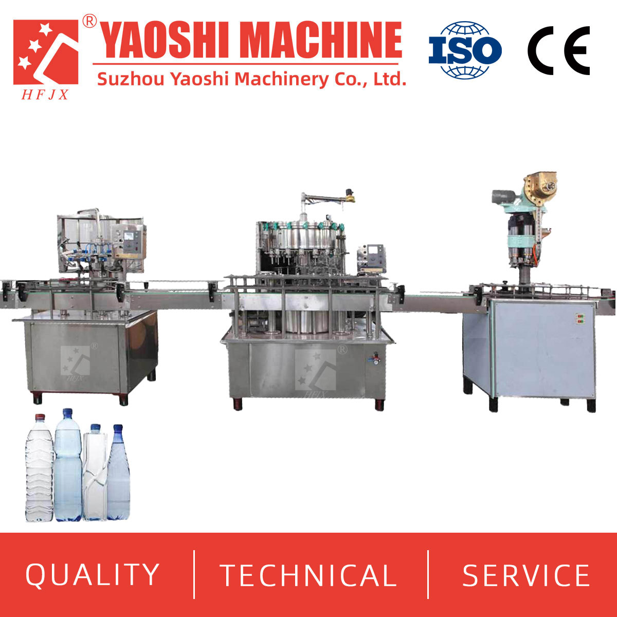
The core water filling equipment should sit within the project's controlled production area, with clear routes for caps, operators, sanitation and maintenance. Yaoshi's CXGF page describes an integrated rinsing, filling and capping machine for bottled water. The final layout must use the selected model's approved general-arrangement drawing, not a category-page illustration.

After capped-bottle inspection, provide the required bottle drying, coding, labeling, accumulation and secondary-packing positions. Packaging materials should enter without crossing the clean bottle infeed. Leave room for label and film replenishment, rejected-product collection, change parts and finished-pack handling.
Size finished-goods staging from the production schedule and dispatch method rather than hourly filler capacity alone. Show pallet movement, forklift turning, loading access and a route that does not pass through the filling area.
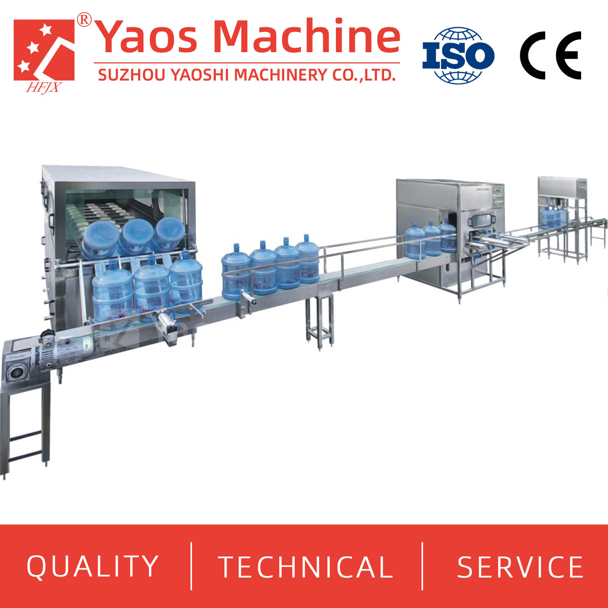
A gallon-water plant requires a different flow because large barrels may return from the market. Separate incoming returned barrels from cleaned barrels and filled product. The layout should move containers progressively from receipt and inspection through preparation, washing, filling, capping and discharge without sending dirty barrels back across the clean side.
Reserve space for unloading, sorting, temporary holding and rejection. The buyer should define whether barrels are new, returned or mixed, and provide drawings and samples for every 3- or 5-gallon format. Damaged and unacceptable barrels need a removal route that does not interfere with production.
Confirm whether cap removal, external brushing, pre-washing and leak inspection are included. These modules need operator access, water and drain connections, and a clear transfer boundary to the main washing section.
Yaoshi's gallon-water solution and QGF product information cover 3- and 5-gallon projects. The detailed QGF page describes integrated washing, filling and capping. Position this equipment around its washing-water, product-water, compressed-air, drainage, cap-supply and maintenance interfaces.

Plan inspection, coding and any confirmed neck-film, bagging, conveyor, rack or pallet-handling stage separately. Large filled barrels need a practical manual or mechanical handling route to storage and dispatch. Do not copy the conveyor assumptions from a small PET bottle line.
| Layout issue | Small PET bottle project | 3- or 5-gallon barrel project |
|---|---|---|
| Container input | Preforms, purchased bottles or onsite-blown bottles | New barrels, returned barrels or both |
| Primary preparation | Bottle blowing or protected empty-bottle feeding | Sorting, cap removal, inspection and project-specific washing preparation |
| Clean transfer concern | Empty-bottle route from blowing or feeding to rinsing | Progression from dirty return area to washed-barrel and filling area |
| Core equipment | Rinsing-filling-capping monoblock | Barrel washing-filling-capping line |
| Downstream flow | Drying, labeling, coding and high-count secondary packing | Inspection, coding and project-specific barrel handling |
| Storage issue | Preforms, bottles, labels, film or cartons and finished packs | Returned barrels, accepted empty barrels, caps and filled-barrel staging |
Published dimensions can support an early block layout, but they are not construction dimensions. Add guarding, operator space, maintenance access, conveyors, pipework and electrical panels. Replace preliminary blocks with approved machine drawings before freezing the building.
| Equipment or model | Published capacity | Published power | Published dimensions | Published weight |
|---|---|---|---|---|
| Water treatment system | 0.5–150 tons/hour | Project-specific | Project-specific | Project-specific |
| CXGF8-8-3 | 2,000 BPH | 3.8 kW | 2300 × 1500 × 2100 mm | 2,800 kg |
| CXGF24-24-8 | 8,000–12,000 BPH | 5.2 kW | 3100 × 2450 × 2300 mm | 6,500 kg |
| CXGF60-60-15 | 28,000–36,000 BPH | 12 kW | 5450 × 3210 × 2300 mm | 12,000 kg |
| QGF-450 | 450 BPH | 7 kW | 4200 × 1600 × 3000 mm | 900 kg |
| QGF-600 | 600 BPH | 8 kW | 4200 × 1600 × 3600 mm | 1,000 kg |
| QGF-900 | 900 BPH | 10 kW | 4200 × 1600 × 4000 mm | 1,500 kg |
The CXGF page publishes a bottle diameter range of 50–115 mm, a bottle height range of 160–320 mm and compressed-air pressure of 0.3–0.7 MPa for the listed series. The detailed QGF page lists a reference barrel dimension of φ276 × 496 mm and a shared air range of 0.45–0.6 MPa and 0.17–0.5 m³/hour. Actual bottle and barrel compatibility, utilities and clearances must be confirmed for the selected machine.
A utility schedule should state quality, pressure, temperature, flow, connected load and operating demand where applicable. The layout should then show how each service reaches the equipment without blocking doors, drains, walkways or removal paths.
| Utility | Layout questions | Buyer information required |
|---|---|---|
| Raw and treated water | Where are tanks, pumps, sampling points and hygienic transfer routes? | Raw-water report, treatment basis and required production flow |
| Electricity | Where are incoming supply, panels, cable trays and isolation points? | Voltage, frequency, phase and local electrical requirements |
| Compressed air | Where are compressors, treatment equipment, receivers and distribution headers? | Pressure, quality and flow available at the machine |
| Blower services | Can high-pressure air and cooling reach an onsite PET blower? | Selected blower's approved utility schedule |
| Drainage | Can wash and cleaning discharge reach suitable drains without crossing dry areas? | Drain locations, elevations, capacity and local discharge conditions |
| Ventilation | How will heat and moisture be managed in treatment, blowing and washing areas? | Room conditions and equipment heat-load information |
Process review: Check the confirmed water process and container sequence from receipt to finished product.
Operation review: Walk through material replenishment, operator tasks, sanitation, rejects and changeovers.
Maintenance review: Confirm access to motors, pumps, valves, panels, molds and removable assemblies.
Installation review: Check unloading, door clearance, lifting, floor loading, foundation work and final positioning.
Issue an action list after each review. Do not release equipment positions while bottle formats, pack patterns, building dimensions or utility locations remain provisional.
For a useful preliminary layout, send the raw-water analysis, required finished-water specification, bottle or barrel drawings, cap details, net output for each format, label and packing method, measured factory drawing and available utilities. For a PET project, state whether bottles will be purchased or blown onsite. For a gallon project, state whether barrels are new or returned and which preparation modules are required.
Ask the supplier to return an equipment list, preliminary flow, dimensioned layout, utility schedule, interface list and scope boundary. These documents should evolve together; changing one machine can alter conveyors, services, maintenance access and total factory length.
No. Required area also depends on treatment, bottle supply, packing, storage, columns, access, utilities, maintenance and the selected equipment drawings.
The arrangement should minimize unnecessary bottle transfer while preserving blower utilities, heat management, mold access, maintenance and the required production-area boundary.
No. A returnable-barrel project may need receiving, sorting, cap removal, external cleaning, washing and heavy finished-barrel handling that a small PET line does not use.
No. Add guards, conveyors, operator stations, door swing, panels, maintenance clearances, piping and component-removal paths.
Coordinate it with the treatment, washing and cleaning process before equipment positions and floor work are frozen.
Define the likely new format or output first, then reserve a realistic extension direction, conveyor connection, utility capacity and service access.
Send a dimensioned building drawing showing clear height, columns, doors, levels, drains, utility entries and the unloading route, together with container and capacity data.
For a new PET bottled-water project or a separate 3- or 5-gallon barrel project, send Yaoshi Machinery your raw-water report, container drawings, required net capacity, packaging method, available utilities and measured factory plan. Request an equipment list, preliminary layout, utility schedule and clear project boundary.
Email tony@yaos.ltd or contact +86 18915689808 by phone or WhatsApp.


+86-512-58530618

Wukesong Road, Sanxing Town, Zhangjiagang City, Jiangsu Province, China